background image


DiGiGrid IOS/IOS-XL / User Guide


17 


C

LIP 

I

NDICATION AND 

S

MALL 

M

ETERS


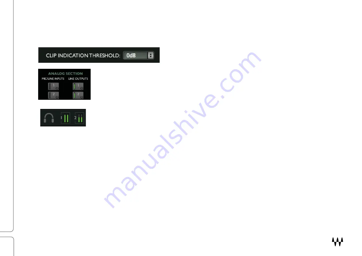
Clip Indication Threshold sets the level where clipping is shown on the meter in the Focus section. The threshold can be 
set to 0 dB, -1 dB, -2 dB, or -3 dB. This setting is global: it affects level indication for all channels—input and output. 

Each channel button—analog or digital, input or output—has a small level meter that indicates 
when signal is present and provides a rough idea of level. A red light on the channel button 
indicates clipping. 


Headphones output levels are indicated in the same manner. 


Summary of Contents for DiGiGrid IOS

Page 1: ...User Guide DiGiGrid IOS IOS XL ...

Page 2: ...9 Manual Device Configuration 10 Automatic Device Configuration 10 Device Firmware 11 IOS IOS XL CONTROL PANEL 12 Controls Page 13 Clock Page 18 System Info Page and About Page 20 Presets 21 USING IOS IOS XL WITH A DAW 22 USING THE IOS IOS XL WITH MIDI 22 SPECIFICATIONS 23 RESETTING THE UNIT 26 INSTALLATION NOTES 26 Waves Inc 2800 Merchants Drive Knoxville TN 37912 USA 1 865 909 9200 www waves com...

Page 3: ...ency The IOS internal SoundGrid DSP server is powered by an Intel i3 processor while the IOS XL uses an Intel i7 Extreme processor A SoundGrid I O device is part of a SoundGrid network SoundGrid is the Waves high speed networking protocol for moving audio clock and other information between a host system and I O devices and between I O devices themselves A SoundGrid host configures the network ass...

Page 4: ...the control panel Input signal present Green signal present 48V phantom power Orange ON Network status indicator Blue device recognized by the SoundGrid network Red device not recognized by the SoundGrid network Yellow Updating White unit malfunction e g firmware did not load properly unit did not boot properly Cycling through colors this LED is also used to identify the unit from the control pane...

Page 5: ...portant which of the Ethernet ports is used to connect to the SoundGrid network USB server service port Recovery reset button MIDI in and out can be linked to Waves applications and to DAWs Digital and clock connections software selected Clock in and out BNC connectors for external Word Clock S PDIF in and out RCA connectors AES in and out XLR connectors Analog connections 8 mic line inputs combo ...

Page 6: ...ed directly to the SoundGrid host computer using a Cat 5e Ethernet cable or better This provides plugin processing and or DAW playback recording via the SoundGrid ASIO Core Audio driver Host computer with SoundGrid application SoundGrid I O device The host computer s LAN port that s connected to the SoundGrid network should be used for SoundGrid only Do not share this port with the internet or oth...

Page 7: ...ce connections are needed use a star network configuration with a 1GB Ethernet switch Only use switches tested and approved by Waves Host computer I O devices 1GB Ethernet switch See this support article for a list of supported switches You can connect and assign up to 16 SoundGrid I O devices to the network depending on the SoundGrid host application All SoundGrid I O devices hosts and servers ar...

Page 8: ... Waves Central to update the host application which also updates the device drivers or install just the missing device driver from Waves Central 1 Waves Central All Waves software is downloaded and installed via the Waves Central application To install a specific device driver launch Waves Central and follow these steps Choose All Products Search for the driver by name Choose the driver and click ...

Page 9: ...rk will be available for assignment This collection of devices is called the Inventory Setup is similar with all hosts identify the host s LAN port select a device slot and use the drop down menu to choose an available device Please consult the user guide of your host application for specific instructions All SoundGrid devices are configured in a similar manner Throughout this section we show DiGi...

Page 10: ...rtain SoundGrid hosts including SoundGrid Studio eMotion LV1 or SuperRack SoundGrid offer an Auto Config tool Once your devices are connected and powered up click Auto Config to start the configuration Auto config chooses the correct LAN port on the host computer and scans the SoundGrid network for devices It then patches the devices to the host We recommend that you let Auto Config take care of t...

Page 11: ...nect the device or turn off the computer before Done appears Once the update is ready turn the device off and on to reset Identify a Device on the SoundGrid Network Click on the ID button to activate a hard to miss LED on the front panel of the corresponding hardware device You can also activate the front panel from the top bar of the device s control panel Grey Compatible firmware Blue Compatible...

Page 12: ...en click the Hardware Control Panel button The driver control panel is located here in the host computer PC C Program Files x86 Waves SoundGrid Driver Control Panel Mac System HD Applications Waves SoundGrid CONTROL PANEL PAGES The Clock and Controls pages are used to set up and manage the unit The About and System Info pages provide information about the unit such as MAC address SOE master firmwa...

Page 13: ...Analog section Digital section Focus section input and output levels and 48V phantom power for selected I O channel are controlled here Controls Page This is where you configure the inputs and outputs of the IOS IOS XL Mic preamps line inputs and outputs digital I O level control and metering ...

Page 14: ... it will appear in the Focus section where preamp parameters are controlled Use the Focus section on the left side to adjust preamp levels and turn the 48V phantom on and off The long meters range from 80 dBFS to 0 dBFS Mic Line knob gain range 0 dB to 52 5 dB in 7 5 dB steps Line knob gain range 0 dB to 52 5 dB in 7 5 dB steps Fine knob digital gain range 0 dB to 7 dB in 0 5 dB steps A clip indic...

Page 15: ...ty reverse button Stereo channels have two Buttons are latching and are colored green when polarity is reversed Digital Input Trim Controls input level from digital sources Separate controls for L R when input is stereo This allows you to control preamps on the fly without leaving your monitor mixer Refer to your host application s user guide for details ANALOG OUTPUT CONTROLS In addition to meter...

Page 16: ...am to the sample rate of the clock that the device is locked to Sample rate conversion is indicated by a yellow light on the channel button DIGITAL SECTION Digital inputs and outputs are selected in pairs Two buttons in the Focus section are used to switch digital input and clock between AES EBU and S PDIF This choice is reflected in the Top Bar illustration ...

Page 17: ...an be set to 0 dB 1 dB 2 dB or 3 dB This setting is global it affects level indication for all channels input and output Each channel button analog or digital input or output has a small level meter that indicates when signal is present and provides a rough idea of level A red light on the channel button indicates clipping Headphones output levels are indicated in the same manner ...

Page 18: ... to assess clock status SOURCE sets the requested clock source Internal The device itself provides the SEO clock External WC Clock is provided by an external device via the Word Clock Input connector Sync over Ethernet The device receives clock from the SoundGrid network Digital IOS IOS XL clocks to incoming digital stream ...

Page 19: ...rnal clock source For example if another SoundGrid I O device is the SOE master and is locked to a word clock device you may choose to receive clock from the same external device over word clock from the master device rather than via network SOE In the event that the selected clock source fails IOS IOS XL has a series of clock fallback layers in this order WC Digital SOE Internal If the device is ...

Page 20: ... description of the device The System Info page contains technical details about the device including MAC address Firmware version and Module version This information is useful for troubleshooting Please have this information handy if you contact Waves technical support concerning the device ...

Page 21: ...and Control panels parameters Save IOS IOS XL presets to use on future sessions or copy them to another computer to duplicate a configuration Click the Identify button to indicate which IOS IOS XL hardware device belongs to this Control Panel Clicking the button causes the Network LED on the front panel of the IOS IOS XL to flash in a rather psychedelic manner ...

Page 22: ...g order Please refer to your SoundGrid host s user guide for details Configure the DAW for SoundGrid 1 Set the DAW playback engine to Waves SoundGrid The SoundGrid driver channels will now appear in the DAW I O preferences and in the Input Output selector in each DAW channel 2 Route the DAW inputs and outputs to SoundGrid Using the IOS IOS XL with MIDI An external MIDI controller can be connected ...

Page 23: ...e inputs on XLR TRS combo 8 channel line outputs on TRS or 25 pin D con 2 headphone outputs with analog level knobs range Off to 15 dB 2 channel AES EBU or S PDIF switchable SRC optional Word Clock I O MIDI I O Internal Ethernet switch with 4 SoundGrid ports RJ45s USB port emergency port to boot server support function Reset switch Settings for different broadcast level formats via jumpers on all ...

Page 24: ...26 dB 150 Ohm source gain 60 dB Harmonic Distortion Typically 0 01 unity gain 10 dB input 1 kHz Frequency Response 0 5 dB 20 Hz to 20 kHz Channel Separation Better than 90 dB 40 Hz to 15 kHz Analog Outputs specifications Maximum Output Level 22 dBu Residual Output Noise 90 dB 20 Hz to 20 kHz Frequency Response 0 5 dB 20 Hz to 20 kHz Output Impedance 50 Ohms Channel Separation Better than 90 dB 40 ...

Page 25: ...r AES59 2012 G C H G C H G C H G C H G C H G C H G C H G C H G Ground C Cold H Hot XLR connectors TRS connectors Positive Tip Negative Ring Signal Ground Sleeve Positive Pin 2 Negative Pin 3 Signal Ground Pin 1 Chassis Ground Case 13 12 11 10 9 8 7 6 5 4 3 2 1 25 24 23 22 21 20 19 18 17 16 15 14 ...

Page 26: ...tions included with the unit The unit is powered from an IEC inlet on the rear This must be connected to an earthed mains outlet using a cable that complies with local approvals and regulations Approvals cover use in ambient air temperature of up to 35 C Operation in higher temperatures should be avoided A 1U space should be left above and below the unit to prevent heat transfer from adjacent equi...

Reviews: