Hardware
Installation Manual
Page 11
4
Installing the ROME Chassis
Installing the ROME Chassis involves the following steps:
1. Mounting the ROME Chassis
2. Mounting the patch panel
3. Cabling (fiber and ground)
Note:
Configuring the ROME equipment is covered in the ROME Administrator Manual.
Option 1
: You will need a total of 20 RUs to properly install ROME chassis, LCU and fiber patch panel in
front of rack.
Option 2
: You will need a total of 11 RUs to properly install the ROME chassis and LCU in front of the
rack and a total of 9U’s to install the fiber patch panel behind the ROME chassis.
4.1
Mounting the ROME Chassis
Orient the front of the ROME Chassis based on configuration.
Take special precautions to ensure that the system remains stable. In particular, mount the first ROME
unit on the lowest set of sliders. Continue to mount ROME units from the bottom up. Two people are
recommended for this step of the process.
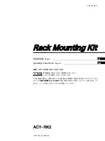
1. Move the ROME Chassis to the lift.
2. Position the ROME unit with the front panel on the the lift (Provide enough room to mount sliders).
3. Route the patch panel through the rack and leave it on the other side of the rack.
4. Extend (slide-out) the sliders arms to maximum extension.
5. Raise the ROME carefully and place it at the appropriate height in between the sliders.
6. Align the extended arms of the sliders with the ROME mounting brackets located on
the left and right side at the top of the ROME.
7. Securely attach the slider arms to the ROME mounting brackets using the
supplied screws (do not use washers or nuts). Attach the chassis with six
(6) phillips head screws on each side. All six (6) screws should be used for
proper support of the ROME chassis slider rail units.
Lifting ROME into Position


