background image

Box Wattsense - Installation Guide

20 / 23

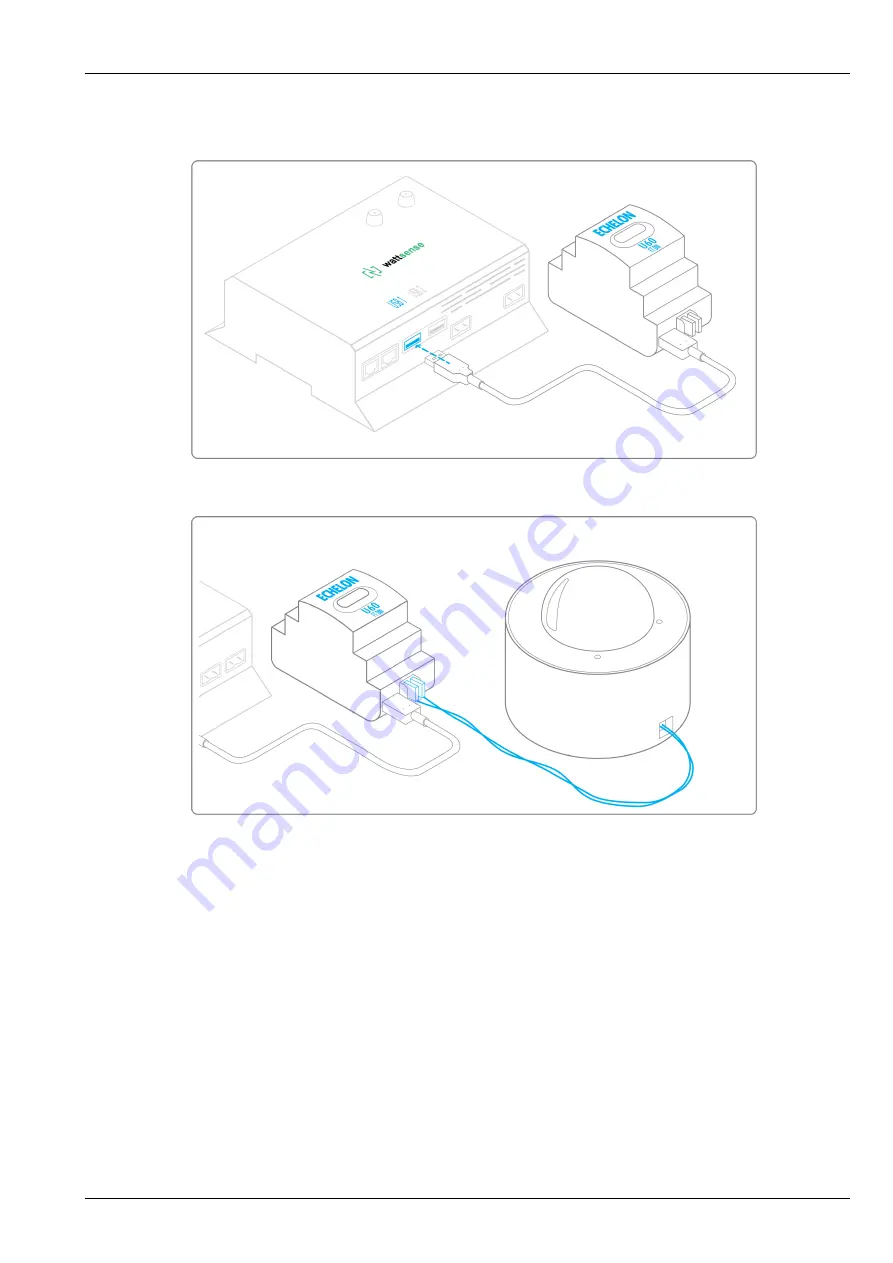
• Connect it to the USB port 1 or 2 in the Box.

• Wire the gateway to different devices as you wish, in serial, star, etc.

To configure each of the equipment

• Retrieve the Neuron-ID that appears on the equipment.

• Write down the Neuron-ID, brand, model of the equipment, and any identifying information. This information will be necessary

for the installation configuration and to retrieve data.

• If you have the NL220 software, export the LON database as an NLC file.

5.5 The equipment communicates in LON IP-852

To connect 1 or several equipment.

• Make sure to have an Ethernet cable.

• Connect the cable to the Ethernet port of the Box ETH1 or ETH2.

Summary of Contents for Box V1.2

Page 1: ...Installation Guide Box V1 2 Universal Building Connector...

Page 2: ...4 1 In case of IP network Except LON 6 4 2 In case of LON IP 852 network 8 4 3 In case of LON FT10 network 9 5 To connect the Box directly to the technical equipment in the absence of a BMS 10 5 1 The...

Page 3: ...ard antenna 1 2 Required material Powerline voltage 100 to 250VAC to 12V 24V DC power supply Cable between the power supply and the Box 2 wires red black 22 AWG minimum section 0 35 mm2 Flat screwdriv...

Page 4: ...ttsense user console and retrieve the login information email address and password Once on site activate the Box on the console How to Log in to the console enter the email and password provided by th...

Page 5: ...to a wall and hook the Box using the notches on the back of the case Screws of maximum 4 mm in diameter with a head of maximum 7 5 mm diameter a spacing of 89 4 mm Use a DC power supply of 12V to 24V...

Page 6: ...Box Wattsense Installation Guide 4 23 Connect the cable to the power supply Check that the Power LED is lit steady green light Wait for ten seconds the Heartbeat LED flashes green light...

Page 7: ...ou can go to the connection step of the Box to the equipment and or the network of the building If the Box does not appear on the console see the GSM Antenna chapter 3 GSM Antenna The Box is supplied...

Page 8: ...e GSM signal is significantly weakened 4 To connect the Box to the BMS Determine the type s of network s associated with the BMS communication protocols between the BMS server and the technical equipm...

Page 9: ...figuration For each device that communicates in Modbus IP From the BMS software perform an extract of the available properties list the data types provided by the different devices to which the BMS ha...

Page 10: ...of LON IP 852 network Connection Make sure to have an Ethernet cable Connect the cable to the Ethernet ports of the Box ETH1 or ETH2 Connect the other end of the cable to the IP 852 server on the LON...

Page 11: ...Write down the neuron ID brand and model of the equipment and any identifying information This information will be necessary for the installation configuration and to retrieve data If you have the NL...

Page 12: ...e as an archive file or as an NLC file 5 To connect the Box directly to the technical equipment in the absence of a BMS Prepare the list of equipment to be connected and their respective communication...

Page 13: ...uide 11 23 Connect the other end of the cable to the equipment Verify that the ETH1 or ETH2 LED lights up To connect 2 devices Make sure to have 2 Ethernet cables Connect the cables to the Ethernet po...

Page 14: ...connect 3 equipment or more make sure to Have an Ethernet cable for the Box Have as many Ethernet cables as equipment to connect Have an Ethernet switch Connect the switch to the power supply Connect...

Page 15: ...ice 192 168 1 3 for the third device and so on Write down the IP address and TCP port and if necessary for certain devices the address of the Slave ID the brand and model of the equipment and any info...

Page 16: ...aximum of 2 networks each grouping equipment with the same communication configuration and assign them to the 2 RS485 ports of the Box If the characteristics of the equipment need to constitute more t...

Page 17: ...Wattsense Installation Guide 15 23 To connect the equipment Caution Do not group together devices with different communication parameters on the same Bus Serial wire the network or each of the 2 netwo...

Page 18: ...Box Wattsense Installation Guide 16 23 Connect the network to an RS485 port of the Box To configure each one of the equipment...

Page 19: ...y identifying information This information will be necessary for the installation configuration and to retrieve data 5 3 The equipment communicates in BACnet IP To connect 1 equipment Make sure to hav...

Page 20: ...ch Connect the power supply to the switch Connect an Ethernet cable to the Ethernet port ETH1 or ETH2 of the Box Connect the other end of this cable to the Ethernet switch Check that the ETH1 or ETH2...

Page 21: ...168 1 1 for the first device then 192 168 1 2 for the second device 192 168 1 3 for the third device and so on Write down the IP address and BACnet port the brand and model of the equipment and any o...

Page 22: ...uipment Write down the Neuron ID brand model of the equipment and any identifying information This information will be necessary for the installation configuration and to retrieve data If you have the...

Page 23: ...Box Wattsense Installation Guide 21 23 Connect the other end of the cable to the IP 852 server of the LON network Verify that the LED ETH1 or ETH2 lights up...

Page 24: ...nd any identifying information This information will be necessary for the installation configuration and to retrieve data If you have the NL220 software export the LON database as an archive file or a...

Page 25: ...al antenna installed on the Box If the signal quality is insufficient move the original antenna out of the cabinet use an RF extension cord with a SMA connector up to 2 meters 1 adhesive support to ho...

Reviews: