background image


13 of 16 

 © 2005          D 704 - 04/05

As in any troubleshooting procedure, it is important to isolate the problem as much as possible. By using the Error Messages located on 
page 14, the troubleshooting process can be greatly simplifi ed. When an error message is displayed on the RMC, refer to the error mes-
sages on page 14 to identify the cause of the error and use standard testing procedures to confi rm the fault. If you suspect an external 
wiring fault, return to step three and carefully check all external wiring connections.
Once the fault has been corrected, press any button on the face of the control to clear the error message.

TEST ROUTINE

The main control functions of the RMC can be tested by pressing and holding the UP button for more than three (3) second. After the 
UP button has been pressed for more than three (3) second, the RMC enters the following sequence.

Step One

The variable speed output is increased from 0% to 100% over 10 seconds.

Step Two

The variable speed output is decreased from 100% to 0% over 10 seconds.

Step Three

The System Pump is turned on for 10 seconds.

Step Four

The Boiler Contact is turned on. After 10 seconds, the Boiler Contact and the 
System Pump contact are turned off. The RMC continues normal operation.

MANUAL OVERRIDE

In the event that the RMC fails to operate, a manual operation switch is located 
on the RMC’s circuit board. When the manual operation switch is set to Man, the 
variable speed injection pump and the system pump outputs are turned on. This 
operation continues until the manual switch is returned to its original position.

FUSE REPLACEMENT

The Variable Speed output of the RMC is fused protected. This fuse is located on 
the circuit board on the back of the RMC. This is a fi eld replaceable item.
Fuse rating: 1 A 1/12 hp, fuse T1 A 250 V

ADJUSTMENT OF SETTINGS

If the outdoor temperature is cold and the rooms are cold, increase the MIX DSGN 
setting by 5°F (3°C) per day.
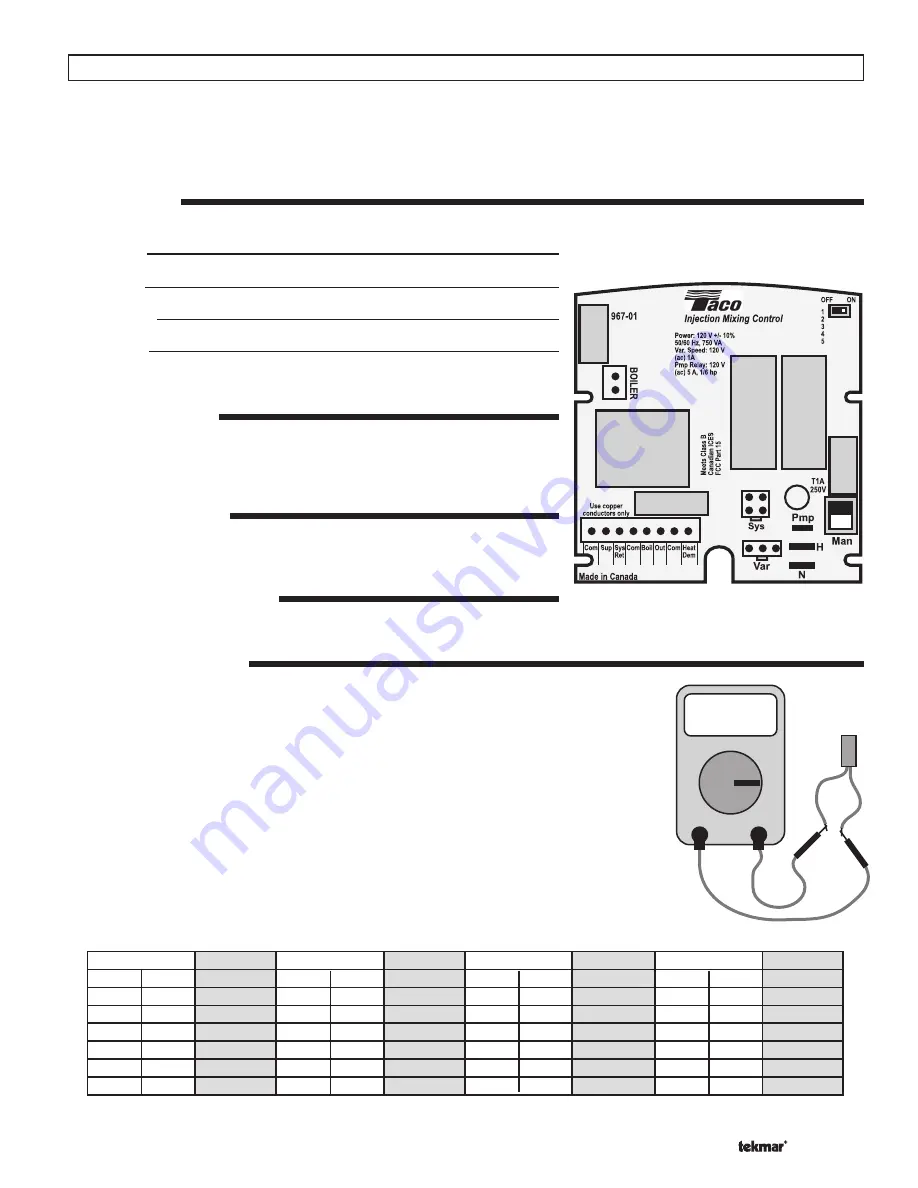
TESTING THE SENSORS

Do not apply voltage to the sensor or to the sensor input of the control as this will result in damage 
to either the sensor, the control, or both the sensor and the control.

A quality testing meter capable of measuring up to 2,000,000 ohms and a good quality digital ther-
mometer are required to test the sensors. If a digital thermometer is not available, place a second 
sensor next to the original sensor and compare the readings.

Begin by measuring the temperature at the sensor location using the digital thermometer. Next, 
measure the resistance of the sensor using the testing meter. Ensure that the sensor is disconnect 
from the control at the time of testing. Using the reference chart below, determine the sensor’s 
temperature. Compare the sensor’s temperature to that measured by the digital thermometer. The 
two temperature readings should be close. 
If the sensors temperature is too high, this can indicate that there is a partial short in the sensor 
wiring. If the sensor’s temperature is too low, this can indicate that there is a loose connection or 
break in the sensor wiring. Isolate and repair the problem. If the problem is isolated to the sensor, 
replace the sensor.

Troubleshooting

OHM

-30
-20
-10

0

10
20

30
40
50
60
70
80

90

100

110

120
130
140

150
160
170
180
190
200

-34
-29
-23
-18
-12

-7

-1

4

10
16
21
27

32
38
43
49
54
60

66
71
77
82
88
93

234,000
165,000

118,000

85,500
62,500
46,000

34,500
26,000
20,000
15,500
12,000

9,300

7,300
5,800
4,700
3,800
3,100
2,500

2,000
1,700
1,400
1,200
1,000

800

Temperature

Resistance

F

C

Ohms

Temperature

Resistance

F

C

Ohms

Temperature

Resistance

F

C

Ohms

Temperature

Resistance

F

C

Ohms

Summary of Contents for tekmar 704

Page 1: ... Extremely versatile the Mixing Station 704 can be set up to operate as an outdoor reset control a setpoint control or a delta T limiting control General Mixing Station 704 Table of Contents TYPICAL PIPING 2 GETTING READY 3 APPLICATION 3 DESIGN PROCEDURE 3 INSTALLATION OF MIXING STATION 704 4 OUTDOOR RESET MODE 5 OUTDOOR RESET SETTINGS 5 SETPOINT AND DELTA T MODE 6 SETPOINT AND DELTA T SETTINGS 7 ...

Page 2: ...ultiple Zone Valves Supply Sensor Boiler Sensor Outdoor Sensor M M Mixing Station 704 Mixing Station 704 Supply Sensor Boiler Sensor Outdoor Sensor Outdoor Sensor Boiler Sensor Boiler Sensor Outdoor Sensor Supply Sensor Radiant Manifold Supply Radiant Manifold Return Supply Sensor Radiant Manifold Supply Radiant Manifold Return Multiple Mixing Station 704s Multiple Temperature System Outdoor Senso...

Page 3: ...jection circulator constant speed system circulator air elimination and the electronics to drive it all With only four piping connections needed the RMB greatly reduces the time and space required for installation The RMB can be set up to operate as an outdoor reset control a setpoint control or a delta T limiting control creating flexibility never seen before in a single unit Check the contents of...

Page 4: ...Return bottom left hand connection as indicated on the plastic cover of the Mixing Station 704 Ensure that a proper isolation valve is installed 5 Connect the Boiler Supply and Boiler Return lines to the boiler loop using standard Primary Secondary piping practices STEP THREE FILLING 1 Fill system with tap water The system must be filled before operating the circulator The bearings are water lubric...

Page 5: ...escribed in the Boiler Operation section The RMC also provides boiler protection as described in the Boiler Operation section DEMAND The RMC requires a demand signal before it will begin operation The RMC can use either a powered or an unpowered demand signal Once a demand signal is received the RMC displays the demand pointer in the display and operates as described above Powered Demand The RMC r...

Page 6: ... fixed supply water temperature This type of application is a setpoint application Examples of setpoint applications include heat pump loops reheat coils and floor warming In specialized applications such as snow melting it is desirable to limit the rate of temperature increase in the system from the system s starting temperature to its operating setpoint This is desired in order to prevent thermal ...

Page 7: ...ot been installed the RMC will Enable the boiler BOILER CONTROL When the RMC controls the boiler the RMC opens and closes the boiler contact in order to control the temperature of the boiler supply water temperature When the RMC is controlling the boiler temperature the RMC will determine the boiler supply water temperature that is required to satisfy the demands of the system The RMC will also de...

Page 8: ...s required When a boiler sensor is connected to the control the RMC is capable of providing boiler protection When providing boiler protection the RMC limits the output of the variable speed injection pump in order to reduce the amount of cool water being returned to the boiler This allows the boiler temperature to increase to a point that avoids flue gas condensation Boiler Protection with Boiler ...

Page 9: ...ten the cable tie as this can cause damage to the sensor The System Supply Sensor 082 is to be installed on the System Supply pipe This sensor is required at all times If a Boiler Sensor 071 is used install the boiler sensor on either the boiler supply or the boiler return Ensure that the DIP switch on the back of the circuit board of the RMC is set to ON if the sensor is installed on the boiler s...

Page 10: ...ired using either a powered signal or an unpowered switch closure Powered Demand If a powered demand is being used connect the switched side of the 24 V ac demand circuit to the Heat Dem terminal of the terminal block Connect the second side of the 24 V ac demand circuit to the Com terminal of the terminal block Unpowered Demand If an unpowered demand is being used connect one side of the demand s...

Page 11: ...ture is displayed when the MIX RET elements are turned on This is the current temperature at the mixing return sensor The mixing return temperature is only displayed if the Outdoor Design temperature is turned OFF and a mixing return sensor is installed Mixing Target Temperature The mixing target temperature is displayed when the MIX TARG elements are turned on This is the temperature the RMC is c...

Page 12: ...mixing target temperature This item is only available if the outdoor design setting is not set to OFF Mixing Minimum Temperature The mixing minimum temperature is the lowest temperature that the control is allowed to use as a mixing target temperature This item is only available if the outdoor design set ting is not set to OFF Boiler Minimum Temperature The boiler minimum temperature item should b...

Page 13: ... on the back of the RMC This is a field replaceable item Fuse rating 1 A 1 12 hp fuse T1 A 250 V ADJUSTMENT OF SETTINGS If the outdoor temperature is cold and the rooms are cold increase the MIX DSGN setting by 5 F 3 C per day TESTING THE SENSORS Do not apply voltage to the sensor or to the sensor input of the control as this will result in damage to either the sensor the control or both the sensor...

Page 14: ...embly away from the body 4 Pull cartridge out of the motor housing 5 Install replacement cartridge making sure that the cover plate is between the cartridge flange and motor 6 Make sure the replacement cartridge corresponds to the full circulator product number A complete parts list is available from your local plumbing supply wholesaler 7 Reassemble the circulator using the new gasket and bolts su...

Page 15: ...l Impeller Non Metallic Shaft Ceramic O Ring Gaskets EPDM ELECTRICAL DATA CHART Voltz 120 Hz 60 Ph 1 Amps 2 RPM 3250 HP 1 40 1 25 DIMENSIONS WEIGHT Ship Weight 18 5 lbs 8 4 kg Motor Type Permanent Split Capacitor Impedance Protected CONTROL ADJUSTMENT MENU Mixing Setpoint Temperature 60 to 185 F 16 to 85 C Maximum Temperature Difference Between Mixing Supply and Return 10 to 70 F 12 to 21 C Off De...

Page 16: ... to tekmar during the warranty period This Limited Warranty does not cover the cost of the parts or labor to remove or transport the defective Product or to reinstall the repaired or replacement Product all such costs and expenses being subject to Purchaser s agreement and warranty with its customers Any representations or warranties about the Products made by Purchaser to its customers which are ...

Reviews: