background image

IOM-T-294

  2205 


© 2022 tekmar

7

Ref

Pressure

Sensor

In

2

3

Gnd

1

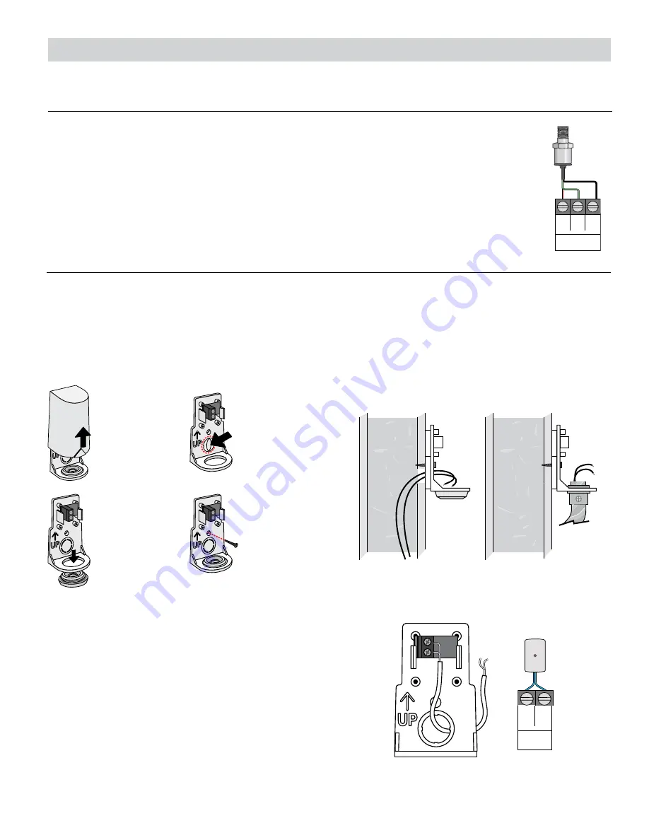
Pressure Sensor 088 (Terminals 1, 2, 3)

An optional Pressure Sensor 088 (sold separately) can connect to the 294 to provide pressure  

monitoring for hydronic systems up to 150 psi (1034 kPa) . The pressure sensor requires the installation 

of a tee with a 

1

8

"-27 NPT port to be installed near the expansion tank .

• Connect the Red reference voltage wire to terminal 1 .
• Connect the Green pressure signal wire to terminal 2 .
 •  Connect the Black power common wire to terminal 3 .

Remove 

cover by  

sliding 

upwards 

away from 

the base.

To wire from 

the back, 

remove the 

knock-out in 

the sensor 

base.

S1

S1

If using  

conduit, 

remove the 

flexible plug 

from the base 

bottom.

S1

S1

Attach the 

base to  

the wall, 

soffit or 

electrical 

box.

S1

S1

•  The 070 can be mounted directly onto a wall with the  

wiring entering through the back or bottom of the enclosure . 

Do not mount the 070 with the conduit knockout facing 

upwards as rain could enter the enclosure and damage  

the sensor .

•  In order to prevent heat transmitted through the wall from 

affecting the sensor reading, it may be necessary to install an 

insulating barrier behind the enclosure .

•  The 070 should be mounted on a wall which best represents 

the heat load on the building (a northern wall for most buildings 

and a southern facing wall for buildings with large south 

facing glass areas) . The 070 should not be exposed to heat 

sources such as ventilation or window openings .

•  The 070 should be installed at an elevation above the ground 

that will prevent accidental damage or tampering .

Outdoor Sensor 070 (Terminals 4, 5)

This section explains how to wire individual devices to the Smart Boiler Control 294 .

Wiring Instructions

•  Connect 18 AWG or similar wire to the two terminals provided 

in the enclosure and run the wires from the sensor to the 

control . Do not run the wires parallel to telephone or power 

cables . If the sensor wires are located in an area with strong 

sources of electromagnetic interference (EMI), shielded cable 

or twisted pair should be used or the wires can be run in a 

grounded metal conduit . If using shielded cable, the shield 

wire should be connected to the Com terminal on the control 

and not to earth ground .

•  Replace the cover of the sensor enclosure .
•  Connect the 2 wires from the outdoor sensor to the Out 

Sens terminals on the 294 (terminals 4 and 5) .

S1

S1

+

Outdoor

Sensor

-

5

4

Summary of Contents for tekmar 294

Page 1: ... Smart Boiler Control 294 IOM T 294 WARNING Please read carefully before proceeding with installation Your failure to follow any attached instructions or operating parameters may lead to the product s failure Keep this Manual for future reference ...

Page 2: ... Menu Screen 19 Navigation 19 Menus 20 Home Screen 20 Settings Menu 21 28 Schedule Menu 29 Notifications Menu 30 Overrides Menu 30 About Menu 32 Help Menu 32 Sequence of Operation 33 Heating Calls 33 Central Heating Operation 33 Domestic Hot Water DHW Operation 35 System Setup and Operation 36 Constant Setpoint Operation 38 Remote Setpoint Call 39 tekmarNet 4 Call 39 Boiler Operation 40 Boiler Mod...

Page 3: ...re are no user serviceable parts inside the control Attempting to do so voids warranty To avoid serious personal injury and damage to the equipment It is your responsibility to ensure that this control is safely installed according to all applicable codes and standards tekmar is not responsible for damages resulting from improper installation and or maintenance Read Manual and all product labels B...

Page 4: ...ada license exempt RSS standard s Operation is subject to the following two conditions 1 this device may not cause harmful interference and 2 this device must accept any interference received including interference that may cause undesired operation The antenna used for this radio must be properly installed and maintained and must provide a separation distance of at least 7 9 inches 20 cm from all...

Page 5: ...n the two bottom screws When choosing the location for the control consider the following Keep dry Avoid potential leakage onto the control RH 90 to 104 F 40 C Non condensing environment Do not expose to operating temperatures beyond 32 104 F 0 40 C Provide adequate ventilation Keep away from equipment appliances or other sources of electrical interference Provide easy access for wiring viewing an...

Page 6: ...lectrocution choc ne pas raccorder à un circuit fonctionnant à plus de 150 V à la terre L 5 4 Out Sens 7 6 Boiler Sensor 9 8 DHW Sensor 11 10 Heat 13 12 DHW 15 14 Setpoint 17 16 tN4 Boiler Bus 19 20 18 Gnd Expansion 22 23 21 A C B Gnd Boiler Modbus 2 3 1 Ref In Gnd Pressure Sens Mod Mod Mod Mod Call Call Call EMS H2061B Smart Boiler Control 294 For product literature Pour la documentation du produ...

Page 7: ...ading it may be necessary to install an insulating barrier behind the enclosure The 070 should be mounted on a wall which best represents the heat load on the building a northern wall for most buildings and a southern facing wall for buildings with large south facing glass areas The 070 should not be exposed to heat sources such as ventilation or window openings The 070 should be installed at an e...

Page 8: ...rsion Well If a Universal Sensor is mounted onto 1 diameter L type cop per pipe there is approximately an 8 second delay between a sudden change in water temperature and the time the sensor measures the temperature change This delay increases con siderably when mild steel black iron pipe is used In general it is recommended that a temperature well be used for steel pipe of diameter greater than 11...

Page 9: ...11 130 54 3 050 200 93 829 5 21 100 221 65 18 13 474 135 57 2 754 205 96 763 0 18 85 362 70 21 11 883 140 60 2 490 210 99 703 5 15 72 918 75 24 10 501 145 63 2 255 215 102 648 10 12 62 465 80 27 9 299 150 66 2 045 220 104 598 15 9 53 658 85 29 8 250 155 68 1 857 225 107 553 A good quality test meter capable of measuring up to 5 000 kΩ 1 kΩ 1000 Ω is required to measure the sensor resis tance In ad...

Page 10: ...oads that do not change with outdoor conditions The setpoint call can be volt free or up to 24 V ac Connect the setpoint call terminals 14 and 15 to the output terminals on a setpoint control or thermostat Central Heat Call Terminals 10 11 A central heat call is required whenever the building requires heating The heat call can be volt free or up to 24 V ac Connect the Central Heat Call terminals 1...

Page 11: ...iler expansion terminal 1 Connect terminal 22 to the boiler expansion terminal 2 Connect terminal 23 Gnd to the boiler expansion terminal 3 Gnd The control can connect to the Internet through Ethernet Connect the Ethernet RJ 45 port on terminal 24 to the building Local Area Network LAN router or network switch using Category 5 cable The control can connect to select boilers that have an available ...

Page 12: ... can be converted to a 0 135 Ω output for a Modutrol IV gas valve actuating motor using a 0 135 Ω tekmar Converter 005 sold separately The 4 to 20 mA output can be converted to a 0 135 Ω output for a V9055 gas valve actuating motor using a 0 135 Ω tekmar Converter 005 sold separately Boiler Control 294 Boiler Control 294 Modutrol IV and V9055 are trademarks and products of Honeywell International ...

Page 13: ...erminal Connect the valve Neutral N to the power source neutral Repeat for additional valves 2 terminals 43 44 valve 3 45 46 and valve 4 terminals 47 48 Ensure each pump is connected to earth ground Combustion Air C A Damper Terminals 49 50 A C A damper requiring up to 230 V ac 5 A 1 3 hp can be switched through terminals 49 and 50 For 24 V ac actuators Connect the power supply red R to terminal 4...

Page 14: ...l 54 to the pump L Connect a wire from the pump N back to the power source neutral Ensure the DHW pump is connected to earth ground Pump DHW 53 54 System Pump Terminals 51 52 A system pump requiring up to 230 V ac 5 A 1 3 hp can be switched through terminals 51 and 52 For simplicity in wiring and troubleshooting a separate breaker for each pump is recommended Connect the power source line wire L t...

Page 15: ...o Unlock and enter your passcode if necessary When first powered on the tekmar logo appears If the display does not turn on please contact your tekmar sales representative or technical support for assistance A custom passcode can be set through the Security menu This is an optional feature If the custom passcode is lost the master passcode is 0294 User Interface Power On Lock Screen ...

Page 16: ...on tekmarNet Blue indicates communication with other tekmarNet devices EXP EXPANSION Blue indicates connection to a expansion control for boilers 5 to 16 BELL NOTIFICATIONS When displayed it indicates an error or warning notification is present Press to go to Menu screen Status icons Error notification Press to go to Boiler Status Press to go to Boiler Supply chart Swipe right to lock screen Swipe...

Page 17: ...tional and is configured through the Settings System Pressure Sensor setting When an output is turned on relay closed the dot is green When an output is turned off relay open the dot is gray When Domestic Hot Water Priority is in effect the dot is green When Warm Weather Shut Down WWSD is in effect the dot is green Manual override are displayed In normal operation the override will display AUTO Th...

Page 18: ... higher number boilers Swipe right to view lower number boilers The circle in blue indicates the boiler firing rate percent or boiler target temperature Press the boiler hour number to go to the Boiler Hours screen Press the boiler cycle number to go to the Boiler Cycles screen When the boiler pump is running or the boiler isolation valve is open the dot is green When the boiler pump is off or the...

Page 19: ...aving X HOME Go to Home screen without saving SAVE SAVE Saves the new setting value CLEAR CLEAR Clears the boiler hours or cycles to 0 SKIP SKIP Skip step in Setup Wizard or Wi Fi Setup BEGIN BEGIN Begin the Setup Wizard NEXT NEXT Go to the next step Menu Screen Navigation ...

Page 20: ...all OUTDOOR TEMPERATURE SENSOR 85 to 149 F 65 0 to 65 0 C Current outdoor temperature as measured by the outdoor sensor is displayed if there is no sensor available or there is a sensor fault DOMESTIC HOT WATER TANK 32 to 266 F 0 0 to 130 0 C Current indirect DHW tank temperature as measured by the DHW sensor is displayed if there is no sensor connected or there is a sensor fault PRESSURE SENSOR 0...

Page 21: ...n WI FI NETWORK Scans for all available networks Select the desired Wi Fi network SSID Then enter the Wi Fi password WATTS ONSITE Register or Deregister Register the control with Watts OnSite to use the web or mobile apps IP CONFIGURATION DHCP or Static Default DHCP Select if the control should receive an automatic IP address from the router DHCP server or use a static IP address IP ADDRESS 0 0 0 ...

Page 22: ... 110 0 C Default 180 F 82 0 C Set the boiler supply water temperature for the heating curve on the typical coldest day of the year WARM WEATHER SHUT DOWN Off or On Default Off Select if the control should shut down the central heating based on the outdoor air temperature WARM WEATHER SHUT DOWN OCCUPIED 35 to 100 F 2 0 to 38 0 C Default 70 F 15 5 C Set the outdoor air temperature at which the centr...

Page 23: ...is System INDIRECT DHW BOILER LIMITING 1 to 16 Default 2 Set the maximum number of boilers to respond to a DHW call The limit does not apply when there are simultaneous central heating or setpoint calls HEATING CALLS CONSTANT SETPOINT CONSTANT SETPOINT Off or On Default Off Select if there are constant setpoint heating loads CONSTANT SETPOINT OCCUPIED 50 to 230 F 10 0 to 110 0 C Default 180 F 82 0...

Page 24: ...gnition BOILER HIGH OUTPUT 10 to 9990 MBTU h Default 400 MBTU h Set the boiler burner s BTU output at full fire Units are in thousands of BTUs per hour MODULATION TYPE 0 10Vdc 4 20 mA Default 0 10 Vdc Set the type of analog signal received by the boiler to modulate the firing rate or target temperature BOILER LOW OUTPUT 10 to 9990 MBTU h Default 80 MBTU h Set the boiler burner s BTU output at low ...

Page 25: ...Automatic Stage Delay is Off PROPORTIONAL INTERSTAGE DIFFERENTIAL 1 to 10 F 0 5 to 5 5 C Default 4 F 2 0 C Set the temperature differential required to turn on the next boiler or next boiler stage Available when using Proportional staging PROPORTIONAL INTERSTAGE ON DELAY 0 5 to 10 0 minutes Default 1 0 minutes Set the boiler run time required before turning on the next boiler or the next boiler st...

Page 26: ...ing tekmarNet is available when connected to a tekmarNet communication system Internet is available when connected to the Internet through Ethernet or Wi Fi PRESSURE SENSOR Off or On Default Off Select if a pressure sensor is installed EXERCISING Off or On Default Off Select if the control should exercise the pumps and valves every 72 hours to prevent seizure BOILER MODBUS Off or On Default Off Se...

Page 27: ...nected to two 294EXP expansion controls BOILER 9 SERVICE CYCLES ALERT 1 to 25000 cycles Default 25000 cycles Set the number of boiler on off cycles above which the control triggers a boiler service alert notification Available when connected to two 294EXP expansion controls BOILER SERVICE HOURS AND CYCLES REPEATED FOR BOILERS 10 TO 12 BOILER 13 SERVICE HOURS ALERT 1000 to 25000 hours Default 5000 ...

Page 28: ...escription SECURITY STEP 1 Set a personal passcode This is required when a passcode has already been set STEP 2 Confirm the personal passcode This is required when a passcode has already been set REQUIRE PASSCODE Off or On Default Off Select if a passcode is required to enter the Home screen PASSCODE Select to change the personal passcode RESET FACTORY RESET Select to load factory defaults for all...

Page 29: ...et the occupied 1 time Select SKIP to ignore the occupied 1 time event UNOCCUPIED 1 TIME 12 00 am to 12 50 pm 0 00 to 23 50 Default 8 00 am 8 00 Set the unoccupied 1 time Select SKIP to ignore the unoccupied 1 time event OCCUPIED 2 TIME 12 00 am to 12 50 pm 0 00 to 23 50 Default 6 00 pm 18 00 Set the occupied 2 time Select SKIP to ignore the occupied 2 time event UNOCCUPIED 2 TIME 12 00 am to 12 5...

Page 30: ... PUMP Off or On Default Off Select to turn on the boiler pump Available in Hand override when Variable Primary Flow is set to Boiler Pumps BOILER ISOLATION VALVE Off or On Default Off Select to turn on the boiler isolation valve Available in Hand override when Variable Primary Flow is set to Isolation Valves MODULATION 0 to 100 Default 0 Set the boiler modulation firing rate signal to fire the boi...

Page 31: ...sioning and also when drying sheet rock and paint in the building Operation of the equipment is dependent on the system WWSD DHW and Setpoint Priority are disabled during Max Heat Max Heat will operate for 1 hour After the timeout period elapses the control will revert back to Automatic mode The max heat override can also be terminated by selecting automatic Hand Override In this mode the control ...

Page 32: ... lists all details about the control This information may be required when contacting tekmar for support Scan the QR code with your mobile phone to be directed to the product website to find specifications manuals and videos About Menu Help Menu ...

Page 33: ...ng curve Heating Curve Terminal Unit Boiler Design Boiler Start Outdoor Design Decreasing Outdoor Temperatures Increasing Water Temperatures Room Occupied and Unoccupied Increasing the Room Temperature setting shifts the heating curve upwards therefore calculating higher boiler target tem peratures Likewise decreasing the Room Temperature set ting shifts the heating curve downwards therefore calcu...

Page 34: ...oiler design boiler maximum supply and boiler minimum supply temperatures The factory defaults can be changed to better match the installed system Locate the Terminal Unit setting in the Central Heating menu TERMINAL UNIT BOILER DESIGN BOILER MAX BOILER MIN Radiant Floor 120 F 49 0 C 140 F 60 0 C 140 F 60 0 C Baseboard 180 F 82 0 C 200 F 93 5 C 140 F 60 0 C Radiator 160 F 71 0 C 180 F 82 0 C 140 F...

Page 35: ...en using a schedule setpoint plus 40 F 22 0 C When using a tekmarNet Setpoint Control the boiler target is set to the device s Exchange Supply setting If there are multiple devices calling for heat the boiler target is set to the highest temperature requirement Programmable Schedule and Away Scene When the programmable schedule is On additional setpoints for the unoccupied period become available ...

Page 36: ...ing system a mixing device is often installed to isolate the high DHW supply temperature from the lower system temperature If a mixing device is not installed high temperature water could be supplied to the low temperature system while trying to satisfy the DHW call This may result in damage to the low temperature heating system The control is capable of providing DHW heating in such a system whil...

Page 37: ... is used to create a DHW call When the DHW sensor fall below the DHW Tank Occupied setpoint minus the Proportional Interstage Differential a DHW call is displayed on the System Inputs screen Boiler Operation The dedicated domestic hot water uses proportional staging for operating the water heaters As the DHW tank temperature progressively drops additional water heaters are staged on Please refer t...

Page 38: ... present On Setpoint priority is provided over the central heating system When there are simultaneous constant setpoint and central heating calls the system pump shuts off to provide priority to the setpoint load When there are simultaneous constant setpoint and tekmarNet calls the system pump can continue to operate If the boilers are unable to maintain the boiler target temperature the tek marNe...

Page 39: ... 5 C 14 7 150 F 65 5 C 16 8 170 F 76 5 C 18 9 190 F 88 0 C 20 10 210 F 99 0 C If a voltage below 1 5 V dc is received the boiler target tem perature is displayed as indicating that there is no lon ger a call for heating A 4 20 mA signal can be converted to a 2 10 V dc signal by installing a 500 Ω resistor between the EMS and EMS terminals EMS Offset The analog voltage signal may drop over the leng...

Page 40: ... be all on the same 294 or 294EXP and cannot span to another 294EXP Example If boiler 1 is set to 4 stage then boiler enables 1 2 3 and 4 are used The Boiler Status displays 25 when stage 1 is on 50 when stage 2 is on 75 when stage 3 is on 100 when stage 4 is on and 0 when the boiler is off Modulating Target Temp The modulating output operates a boiler that interprets an analog input signal as a t...

Page 41: ...o determine the minimum output voltage V dc or current mA that the boiler will successfully operate at For 0 to 10 V dc Minimum Modulation Boiler s Minimum Input Signal x 100 10 V dc For 4 to 20 mA Minimum Modulation Boiler s Minimum Input Signal 4mA x 100 16 mA Example A boiler requires a 1 8 V dc signal to fire the boiler at low fire The boiler can be modulated to 10 V dc where it reaches high f...

Page 42: ...MANUFACTURER SERIES Aerco AM Series Laars OmniTherm Laars MagnaTherm Laars MagnaTherm FT Laars MagnaTherm HTD Laars Pennant Laars NeoTherm Laars NeoTherm LC Lochinvar Crest Lochinvar Crest Outdoor Lochinvar FTXL Lochinvar Knight Outdoor Lochinvar Knight XL Lochinvar PowerFin Raypak MVB Raypak XFIIRE Raypak Xtherm Raypak Xvers Raypak Xvers L All trademarks service marks and company names are the pr...

Page 43: ...is recommended for volume domestic hot water heat ing and applications that require rapid response to heating loads PID Staging PID staging makes use of the following parameters to deter mine when the next boiler is turned on PID Boiler Differential PID Stage Delay PID Boiler Differential Both on off and modulating boilers are operated with a differ ential For modulating boilers the differential n...

Page 44: ... at the minimum firing rate until all available boilers are on If still more boiler output is required all boilers are mod ulated in parallel until they reach 100 firing rate If operating multi stage boilers the control stages all of the low stage out puts in all of the boilers first Once all of the boilers are operating on their low stages the control then operates the second stage in each boiler...

Page 45: ...EXP boiler 4 8 12 or 16 Boiler Plant Flow The control supports the option of having all boilers in the plant to use either a pump or an isolation valve Boiler Pump Select Boiler Pump if each boiler has its own pump to provide flow in the near boiler piping Boiler pump can be selected if the system is piped in reverse return with a single system pump Boiler Isolation Valve Select Isolation Valve wh...

Page 46: ...ercising The control has the option to exercise all pumps and tekmarNet zones zone valves and zone pumps for 10 seconds every three days of inactivity to prevent seizure This is selected by setting Exercising to On Pump Operation Combustion Air Damper The combustion air damper relay closes once a heat call is received and the control has determined that one or more boilers need to be turned on Com...

Page 47: ...This can be changed to one of the applicable North American time zones By default Daylight Savings Time is On Select Daylight Savings Time to Off for regions that do not observe daylight savings time If the Internet is not available the control includes a built in time clock to allow the control to operate on a schedule A battery less backup allows the control to keep time for up to 4 hours withou...

Page 48: ...ove the wires from the DHW sensor terminals then use an electrical multimeter to measure the resistance The resistance should be proportional to the temperature lookup table in the Installation and Operation Manual If the resistance is short circuit check the wires for damage If the wires are OK then replace the Universal Sensor 078 Once the fault is corrected the error clears automatically Domest...

Page 49: ... Smart Boiler Expansion operating boilers 5 to 8 Boilers 5 through 8 will not operate until this error is corrected To correct check that the expansion power light is on If the power light is off use an electrical multimeter to check the power line and neutral terminals for 115 V ac If the expansion power light is on then check the expansion communication wires and Gnd on both the control and expa...

Page 50: ...re did not increase within the boiler alert time There is likely a mechanical failure with either a boiler or circulator that requires immediate attention The control operates normally while this alert is present To reset the alert press the X button to dismiss the error message on the home screen Boiler High Temperature Alert The boiler supply temperature exceeded the boiler high temperature aler...

Page 51: ...eeded the recommended boiler service hours alert interval Once maintenance has been completed the service interval can be reset in the boiler status screen Boiler 01 to 16 Service Cycles Alert The boiler has exceeded the recommended boiler service cycles Once maintenance has been completed the service interval can be reset in the boiler status screen Unsupported tN4 Device An unsupported tN4 devic...

Page 52: ...er than tekmar accident fire Act of God abuse or misuse or has been damaged by modifications alterations or attachments made subsequent to purchase which have not been authorized by tekmar or if the Product was not installed in compliance with tekmar s instructions or the local codes ordinances or if due to defective installation of the Product or if the Product was not used in com pliance with te...

Reviews: