2
•
DO NOT
let the system freeze. System dam-
age may result.
• Install the system on a flat, and level surface.
• The quality of the water to be treated must
meet the feed water guidelines within this
manual. Failure to ensure proper pretreatment
will result in inadequate disinfection. Watts
SmartStream
™
UV systems are engineered
with the highest quality components. If at
anytime a component needs to be replaced,
use only parts recommended and supplied
by Watts.
DO NOT
add components to or
remove components from this system.
The UV lamp is rated for 9000 hours under
normal operating conditions and should be
replaced annually to keep the UV intensity at
the highest possible output. Quartz sleeves
should be cleaned as needed or replaced as
needed to guarantee the highest possible UV
transmittance into the water.
Use only Watts supplied UV lamps and quartz
sleeves for your specific model. Failure to do so
may result in system failure, injury, death, prop-
erty damage and will void all warranty.
DO NOT
use this system in a manner that it
is not intended for. This purifier is only for use
in water applications where the feed water,
installation environment and installation method
meets the requirements within this manual.
The system must be properly sized.
DO NOT
exceed the rated flow rate capacity of the sys-
tem. Flow controllers are available from Watts
to ensure system's rated flow is not exceeded.
Failure to comply with any and all written
instructions for this product may result in sys-
tem failure, injury, death, property damage and
will void all warranty.
Follow all product safety labeling.
NOTICE
Using SmartStream
™
with other water treat-
ment equipment.
SmartStream
™
UV units can be installed as a
final disinfection method within a water treatment
system train or as pretreatment to protect sensi-
tive components, such as reverse osmosis mem-
branes, from bio-films.
The injection of chemicals into the water should be
done on the outlet of the SmartStream
™
system to
ensure UV light degradation of the chemical or the
introduction of turbidity within the UV feedstream
does not occur.
A 5 micron particle filter should always be installed
immediately before the SmartStream
™
system.
Be certain that the feed water meets all criteria
within the Feed Water Specifications section of
this manual.
WARNING
!
Installation Guidelines
•
DO NOT
allow this system to remain ON with-
out water in it for extended periods of time.
•
DO
NOT
install the system near any source
of heat. Also,
DO
NOT
install the system near
any device or break out area that would be
adversely effected by water.
•
DO
NOT
install this system higher in elevation
than 10,000 feet above sea level.
•
DO
NOT
install the system backwards with the
feed water line connected to the outlet.
•
DO
NOT
install where system is exposed to
harsh chemicals or may be subjected to being
struck by moving equipment, carts, mops or
any other item that may cause damage.
•
DO
NOT
install the system outdoors. Keep
system away from moisture, rain, and direct
sunlight. Ambient air temperature must remain
below 122°F and relative humidity must remain
below 90%.
•
DO
NOT
allow the system to freeze.
• The system
MUST
be mounted on a surface
and with mounting hardware that is sturdy
enough to support the weight of the wetted
system.
• The system
MUST
be plugged into an uninter-
rupted power supply that matches the rated
power requirement of the system.
• The system
MUST
be installed in accordance
with all applicable national, state and local
codes.
• A prefilter with a 5 micron minimum particle size
reduction must be installed on the inlet line to
the system. Additional pretreatment may be
necessary so that the feedwater conforms to
the Feed Water Specifications section on page
5.
• Plumbing materials sensitive to UV light, typi-
cally plastic materials, should not be connected
directly to the system. To prevent UV degrada-
tion at the plumbing connection points on the
system, use one foot minimum of copper or
stainless steel plumbing material to connect to
the inlet and to the outlet of the system.
•
IF
water hammer is evident, install water ham-
mer arrestors before the system.
• Always back-up valves and fittings with a
wrench when constructing plumbing to reduce
unnecessary stress on the system and its
plumbing.
Position the system in a suitable location. Make
sure there is enough clearance between the end
of UV chamber and any obstructions, to allow for
the removal of the lamp and quartz sleeve.
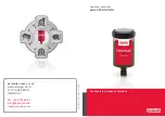
SmartStream
™
UV disinfection systems should be
installed as close as possible to the treated wa-
ter's point of use.
WARNING
!