background image

6

Servicing the Relief Valve

Sizes: 2

1

2

" – 10" (65-250mm)

  1.   Remove the relief valve cover bolts. Note the 909/LF909 is 

designed so that when the bolts are backed off 

1

2

" all the relief 

valve spring load is retained by the bottom plug spring module.


CAUTION

!

 Be sure to verify this before removing all the bolts.
  2.   Remove the cover and diaphragm. The relief valve piston 

assembly can be lifted straight up and out.

  3.  Replace the wiper seal and piston O-ring and apply grease to 

the O-ring.

  4.  To replace the relief valve disc, hold the upper guide fin and 

unscrew the diaphragm pressure plate. It may be necessary to 

lightly tap the cast webs and the pressure plate to loosen. 

Replace with a new disc holder assembly and O-ring. Note: the 

disc rubber is molded into the disc holder and is supplied as a 

disc holder assembly.

  5.  Removal of the bottom plug and spring assembly. During nor-

mal field service there is no need to remove the bottom plug 

spring assembly other than inspection. It can be removed by 

simply unscrewing with a large pipe wrench.


CAUTION

!

The spring as retained on the bottom plug is highly loaded. NO 

attempt should be made in the field to remove the spring. For 

replacement, a complete bottom plug assembly must be obtained 

from the factory.
For further details contact your technical sales representative, see 

back page.

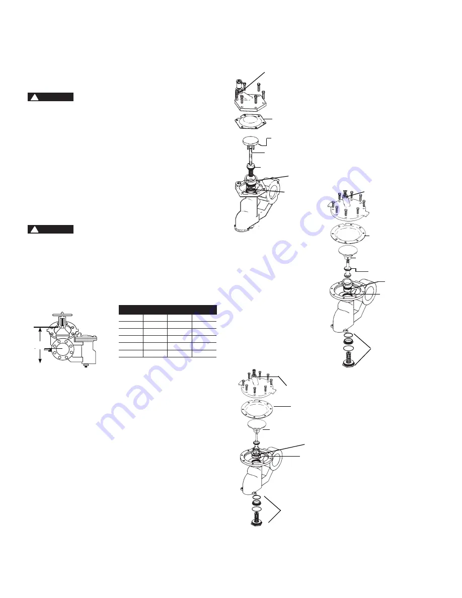
clEaRancE REQuiREd FOR sERVicinG

in.

mm

A

B

2

1

2

 – 3

65-80

10"

11"

4

100

15"

14"

6

150

15"

16"

8

200

23"

21"

10

250

25"

21"

Relief Module

B

Adapter O-ring

Diaphragm

Relief Valve Disc

Relief Valve Piston 

Assembly

Piston O-Ring

Seat

O-ring

Sizes 

2

1

2

" – 3" 

(65 – 80mm)

Diaphragm

Sizes 8", 10" 

(200, 250mm)

Relief Valve Assembly

Seat

O-ring

Plug & Spring 

Assembly

Adapter o-ring

Diaphragm

Sizes 4", 6"  

(100, 150mm) 

8"M1, 10"M1

Relief Valve Piston 

Assembly

Piston seal

Seat

O-ring

Plug & 

Spring Piston 

Assembly

Adapter O-ring

Summary of Contents for LF909

Page 1: ...this Manual for future reference Basic Installation Instructions NOTICE The flange gasket bolts for the gate valves should be re tight ened during in stal la tion as the bolts may have loos ened due to stor age and ship ping High Capacity Relief Series Location and Installation Considerations 1 Backflow preventers must be installed in high visibility locations in order to allow for immediate notic...

Page 2: ...n its proper order The gate valve with the test cock is to be mounted on the inlet side of the backflow preventer The test cock must be on the inlet side of the wedge Please see above Failure to reassemble correctly will result in possible water damage due to excessive discharge from the relief port vent and possible malfunction of the backflow pre venter 8 Installation procedures must comply with...

Page 3: ...e is filled open the downstream shutoff slowly and fill the water supply system This is necessary to avoid water hammer or shock damage G The installation of a Watts air gap with the drain line terminating above a floor drain will handle any normal discharge or nuisance spitting through the relief valve However floor drain size may need to be designed to prevent water damage caused by a cat astrop...

Page 4: ...sh Print Head wait then Push Start Test 7 Open VA then slowly open VB no more than 1 4 turn When relief valve drips push the hold button for 2 seconds Record reading must be 2 psid or more Push Stop Test 8 Close VA and VB Test No 2 Test No 2 Check Valve 9 Install bypass hose between VA and TC 4 Open VA then bleed air by loosening hose connection at TC 4 Tighten hose connection Close VA Push Start ...

Page 5: ...two spring retainers and the stem The spring re tainers are not to be removed for servicing If there is a need to re place the spring spring retainer or stem an assembled module must be obtained from the factory These modules are not interchangeable be sure to replace the first check with a first check mod ule and the second check with a second check module 6 To replace the disc on sizes 21 2 4 65...

Page 6: ...embly 5 Removal of the bottom plug and spring assembly During nor mal field service there is no need to remove the bottom plug spring assembly other than inspection It can be removed by simply unscrewing with a large pipe wrench CAUTION The spring as retained on the bottom plug is highly loaded NO attempt should be made in the field to remove the spring For replacement a complete bottom plug assem...

Page 7: ...place relief valve seat or inlet cover Electrically ground the piping system and or electri cally isolate the device with plastic pipe immediately upstream and down stream of the device B 6 Valve improperly reassembled B 6 If valve is dis as sem bled during installation caution must be exercised to install check springs in their proper location C Valve exhibits high pressure drop C 1 Fouled strain...

Page 8: ...ost of repairing or replacing other property which is damaged if this product does not work properly other costs resulting from labor charges delays vandalism negligence fouling caused by foreign material damage from adverse water conditions chemical or any other circumstances over which the Company has no control This warranty shall be invalidated by any abuse misuse misapplication improper insta...

Reviews: