background image

4

The following Test Procedure is one of several that is rec og nized 

through out the Unit ed States for ver i fi ca tion of the func tion ing of 

backflow  pre ven ters.
The following procedure is not a specific rec om men da tion. The 

Watts se ries of test kits are ca pa ble of per form ing any of the rec og-

nized backflow test procedures.
  A.   Open TC #4 and flush test cocks Nos. 1, 2, and 3 on BF  

assembly, then close TC #4.

  B.   Turn tester on (before connecting hoses). Tester must read all  

zeros. Close VA and VB.

Test No. 1 - Relief Valve

  1. Install high side hose between TC #2 and tester connection A.
  2. Install low side hose between TC #3 and tester connection B.
  3.  Open VB then TC #3. Now open VA then TC #2 slowly. Close 

VA then VB.

  4. Close #2 shutoff valve.
  5.  Observe the apparent first check valve differential pressure (A - 

B).

  6.  Install bypass hose between VA and VB. Open VB and bleed air 

by loosening hose connection at VA. Tighten hose connection 

and close VB.


 Push - Print Head (wait) then Push - Start Test

  7.  Open VA, then slowly open VB (no more than 1⁄4 turn). When 

relief valve drips, push the “hold” button for 2 seconds. Record 

reading (must be 2 psid or more).


 Push - Stop Test

  8. Close VA and VB.

Test No. 2 - Test No. 2 Check Valve

  9.  Install bypass hose between VA and TC #4. Open VA, then 

bleed air by loosening hose connection at TC #4. Tighten hose 

connection. Close VA.


 Push - Start Test

 10. Open VB to reestablish pressure with in the “zone”. Close VB.
 11.  Open VA then TC #4. If relief valve does not drip, record second 

check valve as “closed tight”.

Test No. 3 - Test No. 1 Check Valve

 12.  Open VB to reestablish first check valve differential pressure. 

Close VB. Record pressure dif fer en tial.

 Stop Test (Push Stop Test twice)
 13.  Close test cocks and remove tester, return assembly to normal 

operating condition.

For complete testing information, send for IS-TK-9A or IS-TK-DP/DL.
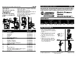
Watts TK-DP

RPZ

Test 1

RPZ

Test 2

RPZ

Test 3

VA

A

B

VB

VA

B

VB

A

VA

B

VB

A

Test Procedure for  

Reduced Pressure Zone 

Backflow Preventers

For repair kits and parts, refer to Backflow 

Prevention Products Repair Kits & Service Parts 

price list PL-RP-BPD on 

www.watts.com

Summary of Contents for LF909

Page 1: ...this Manual for future reference Basic Installation Instructions NOTICE The flange gasket bolts for the gate valves should be re tight ened during in stal la tion as the bolts may have loos ened due to stor age and ship ping High Capacity Relief Series Location and Installation Considerations 1 Backflow preventers must be installed in high visibility locations in order to allow for immediate notic...

Page 2: ...n its proper order The gate valve with the test cock is to be mounted on the inlet side of the backflow preventer The test cock must be on the inlet side of the wedge Please see above Failure to reassemble correctly will result in possible water damage due to excessive discharge from the relief port vent and possible malfunction of the backflow pre venter 8 Installation procedures must comply with...

Page 3: ...e is filled open the downstream shutoff slowly and fill the water supply system This is necessary to avoid water hammer or shock damage G The installation of a Watts air gap with the drain line terminating above a floor drain will handle any normal discharge or nuisance spitting through the relief valve However floor drain size may need to be designed to prevent water damage caused by a cat astrop...

Page 4: ...sh Print Head wait then Push Start Test 7 Open VA then slowly open VB no more than 1 4 turn When relief valve drips push the hold button for 2 seconds Record reading must be 2 psid or more Push Stop Test 8 Close VA and VB Test No 2 Test No 2 Check Valve 9 Install bypass hose between VA and TC 4 Open VA then bleed air by loosening hose connection at TC 4 Tighten hose connection Close VA Push Start ...

Page 5: ...two spring retainers and the stem The spring re tainers are not to be removed for servicing If there is a need to re place the spring spring retainer or stem an assembled module must be obtained from the factory These modules are not interchangeable be sure to replace the first check with a first check mod ule and the second check with a second check module 6 To replace the disc on sizes 21 2 4 65...

Page 6: ...embly 5 Removal of the bottom plug and spring assembly During nor mal field service there is no need to remove the bottom plug spring assembly other than inspection It can be removed by simply unscrewing with a large pipe wrench CAUTION The spring as retained on the bottom plug is highly loaded NO attempt should be made in the field to remove the spring For replacement a complete bottom plug assem...

Page 7: ...place relief valve seat or inlet cover Electrically ground the piping system and or electri cally isolate the device with plastic pipe immediately upstream and down stream of the device B 6 Valve improperly reassembled B 6 If valve is dis as sem bled during installation caution must be exercised to install check springs in their proper location C Valve exhibits high pressure drop C 1 Fouled strain...

Page 8: ...ost of repairing or replacing other property which is damaged if this product does not work properly other costs resulting from labor charges delays vandalism negligence fouling caused by foreign material damage from adverse water conditions chemical or any other circumstances over which the Company has no control This warranty shall be invalidated by any abuse misuse misapplication improper insta...

Reviews: