background image

5

Servicing the Relief Valve


WARNING

!

Before to servicing the relief valve, it is mandatory to shut 

down water system by closing both the inlet and outlet 

shutoff valves and relieving pressure within the assembly by 

opening test cocks No. 2, No. 3, and No. 4.

DO NOT REMOVE SPIDER BUSHING FOR SERVICING

1.  Detach the activation module, if installed, from the flood sensor.
2.  Use a #2 Phillips screwdriver to remove the sensor from the 

relief valve.

3.   Disconnect the hose from the bottom cover plate to the  

relief valve.

4.   An O-ring seals the relief valve body to the main housing. 

Avoid tightening the connection beyond firm hand tightening. 

Loosen the relief valve by hand to remove it, then unscrew the 

relief valve from the housing.

5.   Remove the cover plate of the relief valve by detaching the 

four connecting screws.

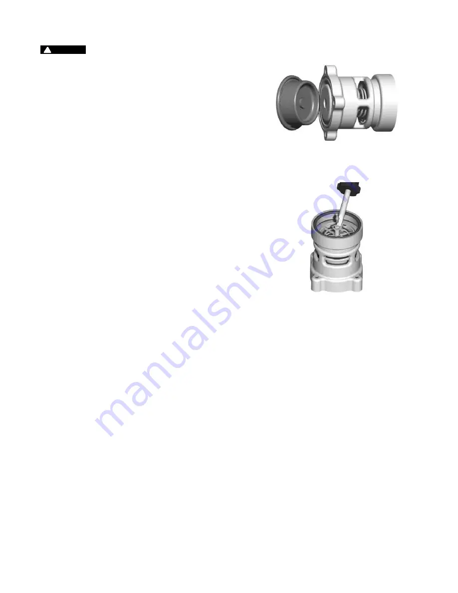
6.   Remove the rubber diaphragm from the relief valve. Notice 

how the diaphragm is configured to reinstall it in the same 

manner. The hard rubber tab in the diaphragm fits into a  

similar socket in the head of the piston. (See Figure A.)

7.   Hold the relief valve in both hands with the threaded end 

up and both thumbs on the head of the piston. Push up on 

the piston until the piston shaft with the attached E-clip is 

exposed. Remove the E-clip. (See Figure B.)

8.   Remove the piston and spring from the relief valve housing and 

thoroughly clean all parts including the diaphragm. Inspect all 

rubber parts and replace any that are damaged.

9.   Reverse the order of these steps to reassemble the parts  

and housing.

Figure B

Figure A

Summary of Contents for AMES Colt C400

Page 1: ...y in compliance with local codes but at least once per year or more as service conditions war rant All products must be retested once maintenance has been performed Corrosive water conditions and or u...

Page 2: ...on the assembly and the local water authority approves the installation The assembly should be installed with adequate clearance around the valve to allow for inspection testing and servicing Ensure a...

Page 3: ...re C 5 Remove the check 2 module with the same instructions as in step 4 For servicing 6 checks see the maintenance instructions for valve sizes 8 to 10 6 To clean or inspect either check module inser...

Page 4: ...service hole and thread in the service bolt by hand until it contacts the linkage See Figure A 4 Continue to thread in service bolt with the wrench until the service hole in the linkage is aligned wi...

Page 5: ...d to remove it then unscrew the relief valve from the housing 5 Remove the cover plate of the relief valve by detaching the four connecting screws 6 Remove the rubber diaphragm from the relief valve N...

Page 6: ...Open valves B and C bleeding to atmosphere Then closing valve B restores the system to a normal static condition Observe the pressure differential gauge If there is a decrease in the indicated value c...

Page 7: ...ng First Check Module Relief Valve Second Check Module Troubleshooting PROBLEM CAUSE SOLUTION Relief valve discharges water while system is not flowing Check 1 is fouled Remove and clean check 1 Relie...

Page 8: ...nt In the event of such defects within the warranty period the Company will at its option replace or recondition the product without charge THE WARRANTY SET FORTH HEREIN IS GIVEN EXPRESSLY AND IS THE...

Reviews: