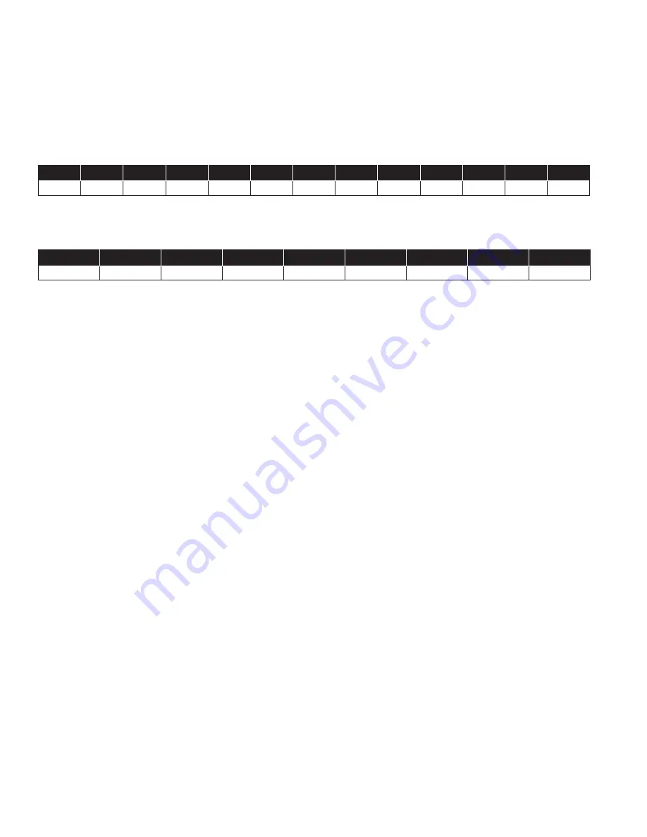
background image

Size (in)

3

4

6

8

10

12

16

20 & 24

P/N

0677-01

0677-01

0677-02

0677-03

0677-04

0677-05

0677-09

0677-11

8.    


Replace Seat Disc, Diaphragm and Spacer Washers provided in Main Valve repair kit (refer to Table 2 or 3 for correct repair kit part     


number). Re-assemble in the reverse order of disassembly.

9.    Re-Install Disc and Diaphragm Assembly in the valve, taking care not to damage the lower guide area in the center of the valve 

seat.

10.  Re-install Cover Spring. Replace Valve Cover and tighten Cover Nuts in a crossing pattern to ensure even distribution. Test the Disc 

and Diaphragm Assembly for smooth travel by following the Freedom of Movement Test procedure in previous section.

11.  Test the integrity of the Seat Seal by following the Seat Seal Test procedure in previous section.
12.  Return valve to service by following instructions on the Technical Bulletin matching the valve function.

Size (in)

1


1/4

1


1/2

2

2


1/2

10 

12 

14 

16 

P/N

0677-01

0677-01

0677-02

0677-03

0677-04

0677-05

0677-06

0677-07

0677-08

0677-09

0677-10

0677-11

10          IOM-A-ACV-910_610   2115 

EDP# 1917028 

© 2021 Watts

Table 3: Reduced Port Valve (605GD/605AD) Repair Kits

Table 2: Full Port Valve (905GD/905AD) Repair Kits

Summary of Contents for AMES 605AD

Page 1: ...ormation provided You are required to consult the local building and plumbing codes prior to installation If the information provided here is not consistent with local building or plumbing codes the l...

Page 2: ...ing installation to protect the piping circuit from damage Only remove the pilot control system from the valve if necessary Tubing and fittings should be kept clean and replaced exactly as removed Con...

Page 3: ...he valve Take proper precautions to protect your space from water damage STEP 1 Start with the upstream and downstream isolation valves in your system closed labeled 1 and 2 in Figure 1 respectively B...

Page 4: ...e valve number one in Figure 2 below Air is vented through the air bleed valve or loosened fitting Tighten the fitting when liquid begins to vent Repeat the process until no air is trapped in the syst...

Page 5: ...id increase in pressure possibly higher than the desired set point turn the adjustment screw IN clockwise decreasing the rate of opening STEP 7 Note If the main valve comes equipped with a closing spe...

Page 6: ...ve specification sheets for approximate cover capacity A continuous flow of water from the open port indicates a damaged diaphragm or loose disc diaphragm assembly Disassemble valve and replace diaphr...

Page 7: ...embly by partially opening from full closed position Improperly configured opening speed control if equipped Adjust opening speed control to verify functionality adjust as required Standard setting fo...

Page 8: ...Remove cover nuts and washers 3 Remove the cover If cover is not free to be removed loosen it by tapping upward along its outside edge with a dull cold chisel pic tured above a Large valves may requi...

Page 9: ...e brush or by using a Mineral Dissolving Solution Inspect parts for wear and replace if necessary 7 Inspect valve seat If seat is not damaged removal is not necessary Valve seats 6 and smaller are thr...

Page 10: ...Nuts in a crossing pattern to ensure even distribution Test the Disc and Diaphragm Assembly for smooth travel by following the Freedom of Movement Test procedure in previous section 11 Test the integ...

Page 11: ...Stem Washer ASTM A276 304 Stainless Steel 10 Diaphragm Washer ASTM A536 65 45 12 Epoxy Coated Ductile Iron 11 Diaphragm Buna N Nitrile 12 Disc Retainer ASTM A536 65 45 12 Epoxy Coated Ductile Iron 13...

Page 12: ...sts resulting from labor charges delays vandalism negligence fouling caused by foreign material damage from adverse water conditions chemical or any other circumstances over which the Company has no c...

Reviews: