CONTROL PANEL OPERATING PROCEDURES
3-4
3.3. CONTROL PANEL MENUS
The Control Panel incorporates an extensive
menu structure which permits the operator to set
up, and configure the unit. The menu structure
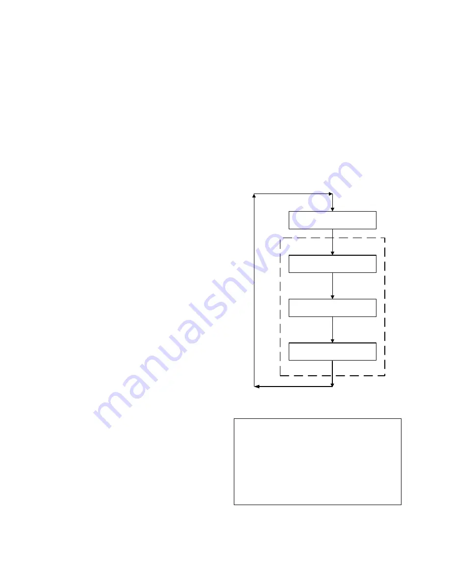
consists of four major menu categories as
shown in Figure 3-2. Each of the menus shown,
contain options which permit operating parame-
ters to be viewed or changed. The menus are
protected by a password to prevent unauthor-
ized use.
Prior to entering the correct password, the
options contained in the Operating, Setup,
Configuration and Tuning Menu categories can
be viewed. However, with the exception of
Internal Setpoint Temperature (Configuration
Menu), none of the viewable menu options can
be changed.
Once the valid password (159) is entered, the
options listed in the Setup, Configuration and
Tuning Menus can be viewed and changed, if
desired.
3.3.1. Menu Processing Procedure
Accessing each menu and option is
accomplished using the Menu Keys shown in
Figure 3-1. Therefore, it is imperative that you
be thoroughly familiar with the following basic
steps before attempting to perform specific
menu procedures.
1. The Control Panel will normally be in the
Operating Menu and the VFD will display the
current unit status. Pressing the
▲
or
▼
arrow key will display the other available data
items in the Operating Menu.
2. Press the
MENU
key. The display will show
the Setup Menu which is the next menu
category shown in Figure 3-2. This menu
contains the Password option which must be
entered if other menu options will be
changed.
3. Continue pressing the
MENU
key until the
desired menu is displayed.
4. With the desired menu displayed, press the
▲
or
▼
arrow key. The first option in the
selected menu will be displayed.
5. Continue to press the
▲
or
▼
arrow key until
the desired menu option is displayed.
Pressing the
▲
arrow key will display the
available menu options in the Top-Down
sequence. Pressing the
▼
arrow key will
display the options in the Bottom-Up
sequence. The menu options will wrap-
around after the first or last available option
is reached.
6. To change the value or setting of a displayed
menu option, press the
CHANGE
key. The
displayed option will begin to flash. Press
the
▲
or
▼
arrow key to scroll through the
available menu option choices for the option
to be changed. The menu option choices do
not wrap around.
7. To select and store a changed menu item,
press the
ENTER
key.
OPERATION
SETUP
CONFIGURATION
TUNING
PASSWORD
Figure 3-2. Menu Structure
NOTE:
The following paragraphs provide brief
descriptions of the options contained in
each menu. Refer to Appendix A for
detailed descriptions of each menu option.
Factory Default settings for all menu options
are listed in Appendix E. Refer to Appendix
B for listings and descriptions of displayed
startup, status and error messages.
Summary of Contents for AERCO Benchmark 2.0LN
Page 9: ... This page intentionally blank ...
Page 19: ... This page intentionally blank ...
Page 29: ... This page intentionally blank ...
Page 35: ... This page intentionally blank ...
Page 41: ...5 1 This page intentionally blank ...
Page 47: ...SAFETY DEVICE TESTING 6 1 This page intentionally blank ...
Page 70: ...APPENDIX C C 1 Temperature Sensor Resistance Chart Balco ...
Page 77: ...APPENDIX F F 2 ...
Page 78: ...APPENDIX F F 3 ...
Page 79: ...APPENDIX F F 4 ...
Page 92: ...APPENDIX G G 5 ...


