background image

11

ServiceGuide-ACV-Assure  

2133 

EDP# 1917123 

© 2021 Watts

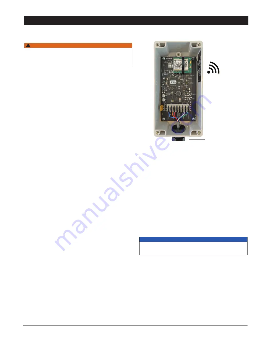
When identifying a location to mount the Cellular Gateway, 

the device must be placed away from large metal objects and 

structures that can block cellular signal. Additionally, the cellu-

lar antenna is located on the upper right inner side wall of the 

enclosure. When mounting, ensure that this part of the device is 

away from any walls, wires, pipes, or other obstructions,  

especially anything metallic.
1.  Before mounting, apply power to the Cellular Gateway to 

ensure there is adequate cell coverage. On startup, the CELL 

LED will blink at a rate of 1sec. This indicates it is searching 

for a cell connection. Once connected it turns steady blue. 

If connection is poor, it will blink with short OFF pulse every 

second. If there is a poor or no connection, find a new  

location. 

Once cell coverage is established, disconnect 

power from the Cellular Gateway before proceeding.

2.  Mount the Cellular Gateway at the selected location, using the 

mounting tabs and screws provided with the kit. Screws to 

attach the unit to the wall are not included.

3.  Using the four-conductor cable supplied with the kit, connect 

the Control Box to the Cellular Gateway. Route wires from  

the WIRELESS terminals of the Control Box through the 

Cellular Gateway’s wiring gland and connect to the matching 

terminals.

  PWR to PWR
  GND to GND
  Input 1: Blue/Orange Wire
  Input 2: White/Green Wire
   Six feet of cable is supplied with the unit, but the Cellular 

Gateway can be located up to 100 feet away from the 

Control Box. If additional wire is used it must meet the 

required rating for the Control Box (300V, 22 AWG).

4.  To prevent water or dust from entering the Cellular Gateway, 

Control Box & Relay Box, tighten all wiring glands.

5. Apply power to the Control Box and Cellular Gateway.


1.  

Startup

 – Upon startup, the POWER LED will light up a 

steady green to indicate power is supplied. The Cellular 

Gateway will automatically go into its startup sequence. 

During the startup sequence, the CELL and IoT LED will blink 

blue, indicating the Cellular Gateway is searching for a cellular 

connection. This may take up to 10 minutes. Once the cellu-

lar and cloud connections are established, the CELL LED and 

IoT LED will be steady blue.

2.  

Cellular Connection

 – After the startup sequence is  

completed, the CELL LED will be a steady blue if there is a 

good connection. It will blink with short OFF pulses if there is 

a poor connection. 

3. 

 IoT  Connection

 – If there is a cloud connection, the IoT LED 

will be a steady blue. IoT LED will blink if cloud connection  

is lost or not established. It will continue trying to connect 

indefinitely.

4.  

Test Button

 – When cellular and Cloud connections have 

been made, you can send a test message through the 

Syncta app by pressing the TEST button.

5.  

Reset Button

 – You can reset the Cellular Gateway and 

restart the startup sequence by pressing the RESET button. 

This will cause all on-going operations to cease.

Installation and Set-Up

Installing the Cellular Gateway

Setting Up the Cellular Gateway

WARNING

!

Ensure all power supply to the Cellular Gateway is turned off before 

making any connections to the Cellular Gateway. Failure to do so may 

result in electrocution, personal injury, and/or death.

Cellular Gateway

Cellular 

Connection to 

Internet

Wired to Control Box

NOTICE

If there is no cloud connection, users will not receive notifi-

cations via Syncta.

Summary of Contents for ACV Assure

Page 1: ...ications Typical 3 4 Control Box and Cellular Gateway Installation 5 Component Installation Details 6 Supplied Snubber Installation for the Pressure Sensor 6 Watertight Splice for the Pressure Transdu...

Page 2: ...property damage or damage to the equipment This pictorial alerts you to the need to read the manual This pictorial alerts you to electricity electrocution and shock hazards Learn how to properly and...

Page 3: ...ServiceGuide ACV Assure 2133 EDP 1917123 2021 Watts Applications Typical Solenoid Control Pressure Reducing ACV ACV Assure hardware installation on a 165 ft water tower base 165 ft Water Storage Towe...

Page 4: ...ure 2133 EDP 1917123 2021 Watts Applications Typical Pressure transducer installed in ground storage tank Remote installation with solar panel for power Vault with solar panel Inside vault Battery box...

Page 5: ...he packaging foam to secure the Controller on both sides against the Control Box not shown Use the mounting feet which are included in the shipping box Mount in a good Cellular signal area Mount to a...

Page 6: ...e Flow Switch Connector Cable Pressure Sensor Teflon Tape Snubber Teflon Tape Component Installation Details Cellular Gateway Wiring Flow Switch Wiring Pressure Sensor installation must include the su...

Page 7: ...essure Transducer When Control Cable Length Exceeds 9ft Crimp butt connector PVC red 22 18ga Tubing length is 1 to 1 from dimension X X 3 8 ID adhesive lined heat shrink tubing 3 to 1 ratio Place tubi...

Page 8: ...roller 24VDC Power Supply 120 VAC 2 Conductor 18 20 AWG To Pressure Sensor 2 Conductor 18 20 AWG Control Cable 6 conductors 22 AWG PVC conductor insulation material for the Cellular Gateway Flow Switc...

Page 9: ...VC conductor insulation material for the Cellular Gateway Flow Switch Pressure Controller 24VDC Power Supply To Solenoid 2 Conductor 18 20 AWG 120 VAC 2 Conductor 18 20 AWG To Pressure Sensor 2 Conduc...

Page 10: ...Solenoid 2 Conductor 18 20 AWG 120 VAC 2 Conductor 18 20 AWG To Pressure Sensor 2 Conductor 18 20 AWG Relay Box Wiring for ACV Zone Control Control Cable 6 conductors 22 AWG PVC conductor insulation m...

Page 11: ...ing for the Control Box 300V 22 AWG 4 To prevent water or dust from entering the Cellular Gateway Control Box Relay Box tighten all wiring glands 5 Apply power to the Control Box and Cellular Gateway...

Page 12: ...uence When the Cellular Gateway powers up the device goes through a startup sequence Below is the startup sequence that the device will go through if everything is working correctly Operation This sec...

Page 13: ...on to the cloud COLOR STATE DEFINITION SOLUTION Steady Blue There is a connection to the Watts Cloud N A Blinking There is not a connection to the Watts Cloud Trying to establish connection See No Con...

Page 14: ...way and restart the device This will cause all ongoing operations to cease Note You can also perform a full reset by removing power to the Cellular Gateway for 10 seconds and then plugging it back in...

Page 15: ...r other obstructions such as an electrical box Possible Cause 2 The location has poor cellular reception Solution 2 Move your Cellular Gateway to a different location and check to see that the CELLULA...

Page 16: ...use If the Cellular Gateway is plugged in and the POWER LED is off the 24Vdc GND wiring polarity inside the Cellular Gateway might have been accidentally swapped Solution Use the instructions below to...

Page 17: ...commissioning latch the Control Box cover closed and use the supplied tamper resistant screw and nut M4 x 16mm to secure the Control Box closed Assemble the cover and use 2 supplied tamper resistant...

Page 18: ...ssets Register the Syncta device https app syncta com en connected onboarding welcome Log in to the Syncta account https app syncta com users sign_in already logged into your account go to https app s...

Page 19: ..._ _ _ _ _ _ _ _ _ _ _ _ _ _ _ _ _ _ _ _ _ _ _ _ _ _ _ _ _ _ _ _ _ _ _ _ _ _ _ _ _ _ _ _ _ _ _ _ _ _ _ _ _ _ _ _ _ _ _ _ _ _ _ _ _ _ _ _ _ _ _ _ _ _ _ _ _ _ _ _ _ _ _ _ _ _ _ _ _ _ _ _ _ _ _ _ _ _ _ _...

Page 20: ...product does not work properly other costs resulting from labor charges delays vandalism negligence fouling caused by foreign material damage from adverse water conditions chemical or any other circum...

Reviews: