6
Test Procedures
Reduced Pressure Zone Assemblies must be inspected and
tested periodically, in accordance with local codes, to ensure
proper operation of check valves within the unit.
A differential pressure gauge is recommended for Test No. 1
rather than a manometer for the following reasons: It utilizes
minimum time to perform the test. It eliminates the necessity of
closing the inlet ball valve which could release pipe scale and
foreign matter into the backflow preventer. Only a slight amount
of water is ‘spilled’ in test. A mercury manometer could cause a
pollution hazard.
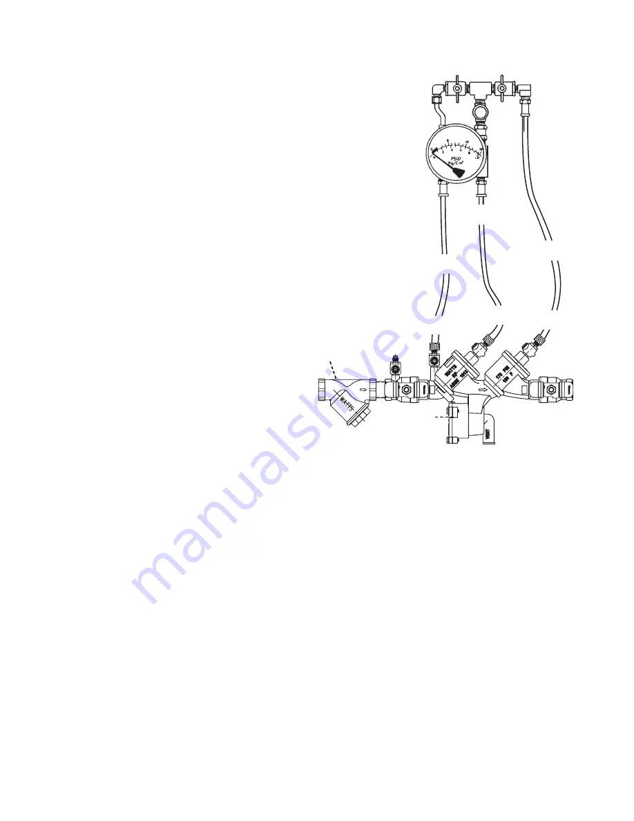
Test Set Up
Reduced Pressure Zone Assembly
Close Valves A, B and C on Test Kit.
Connect high side hose to test cock #2
Connect low side hose to test cock #3. Close shutoff #2.
Open test cocks #2 and #3.
Open vent valve C.
Open ‘high’ valve A and bleed to atmosphere until all the
air is expelled.
Close valve A. Open ‘low’ valve B and bleed to atmosphere until
all air is expelled. Close ‘low’ valve B. Close ‘vent’ valve C.
Connect vent hose to test cock #4.
Test Procedure
Reduced Pressure Zone Assembly
Field Test Equipment Required
Watts Test Kit
Test No. 1
Purpose:
To test Check Valve No. 2 for tightness against reverse
flow.
Requirements: Valve must be tight against reverse flow under all
pressure differentials. Slowly open the ‘high’ valve A and the
‘vent’ valve C, and keep the ‘low’ valve B closed. Open test
cock #4. Indicated pressure differential will decrease slightly. If
pressure differential continues to decrease (until the vent opens)
check valve #2 is reported as ‘leaking’.
Test No. 2
Purpose:
To test shutoff #2 for tightness.
Requirements: After passing Test No. 1, continue to Test No. 2
by closing test cock #2. The indicated pressure differential will
decrease slightly. If pressure differential continues to decrease
(approaching “zero”), shutoff #2 is reported to be “leaking”.
Test No. 3
Purpose:
To test Check Valve No. 1 for tightness.
Requirements: Valve must be tight against reverse flow under all
pressure differentials. Close ‘high’ valve A and open test cock
#2. Close test cock #4. Disconnect vent hose at test cock #4.
Open valves B and C, bleeding to atmosphere. Then closing
valve B restores the system to a normal static condition.
Observe the pressure differential gauge. If there is a decrease in
the indicated value, Check Valve No. 1 is reported as “leaking”.
Test No. 4
Purpose:
To test operation of pressure differential relief valve.
Requirements: The pressure differential relief valve must operate
to maintain the “zone” between the two check valves at least 2
psi (14 kPa) less than the supply pressure. Close ‘vent’ valve C.
Open ‘high’ valve A. Open the ‘low’ valve B very slowly until the
differential gauge needle starts to drop. Hold the valve at this
position and observe the gauge reading at the moment the first
discharge is noted from the relief valve. Record this as the open-
ing differential pressure of the relief valve.
Note: It is important that the differential gauge needle drops
slowly.
Close test cocks #2 and #3. Use ‘vent’ hose to relieve pressure
from test kit by opening valves A, B and C. Remove all test
equipment and open shutoff #2.
Strainer
Test Cock
No. 1
Test Cock
No. 2
High Hose
(Color - Yellow)
Auxiliary
Test Cock
Ball Type
(A) Test Valves (C)
(B)
Needle
Valve
Test Cock
No. 3
Test Cock
No. 4
Shutoff
No. 2
Relief
Valve
Low Hose
(Color - White or Red)
Vent Hose
(Color - Blue)
919QTS
Summary of Contents for 919 Series
Page 7: ...7 NOTES ...