2
Basic Installation Instructions
1
⁄
4
" – 2" (8 – 50mm)
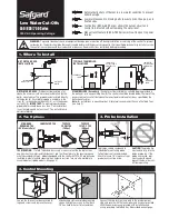
Series 919 Reduced Pressure Zone Assemblies
Air Gap
Strainer
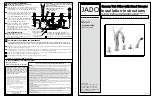
Indoor Installation
For indoor installations, make sure the Series 919 is easily
accessible to facilitate testing and servicing. Do not install in
concealed locations. If the location of the Series 919 is parallel
and close to the wall, make sure the test cocks are easily
accessible, and the drain line can adequately drain if required.
An air gap and drain line (see literature ES-AG/EL/TC) are piped
from the relief valve connection as shown, allowing evidence of
discharge to be clearly visible and preventing the occurrence of
water damage.
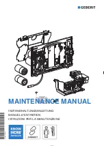
Outdoor, Above Ground Installation
For outdoor installations, it is recommended that you install the
Series 919AQT where there are no freezing conditions and
above ground whenever possible.
You must install the Series 919 in an accessible location to
facilitate testing and servicing. The installation must also allow
for adequate drainage from the air gap and the discharge line
if needed.
WA R N I N G
1. Do not allow the drain line to empty directly into a drainage
ditch, sewer system, or sump.
2. Do not install the Series 919 in any location where any part
of the unit could become submerged in standing water.
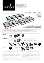
Parallel Installation
For parallel installations, you can install two or more small sized
Series 919's (when approved) to serve a large supply pipe main.
You can use this type of installation in an application where
increased capacity beyond that provided by a single valve is
required. Additionally, this type of installation permits testing
and/or servicing of a single valve without shutting down the
complete line.
The number of Series 919 units installed in parallel should be
determined by the engineer's judgement, based on the operating
conditions of a specific application.
NOTE:
The total capacity of all the units installed in the application
should equal or exceed that required by the system.
Now available, WattsBox Insulated Enclosures,
for more information, send for literature ES-WB.
FIBERGLASS WattsBox
Min. 12"
Annual inspection of all water system safety and control valves
is required and necessary. Regular inspection, testing and
cleaning assures maximum life and proper product function.
Meter
Indoor Installation
Outdoor Installation
Parallel Installation
12" (300mm) Minimum
(refer to local codes)
Watts
1
⁄
4
" – 2" (8 – 50mm) 919
Watts
1
⁄
4
" – 2"
(8 – 50mm)
919AQT
Watts
1
⁄
4
" – 2" 919
(8 – 50mm)
Min. 12" (300mm)
Summary of Contents for 919 Series
Page 7: ...7 NOTES ...