


Now available, WattsBox Insulated Enclosures,
for more information, send for ES-WB or ES-WB-T.
FIBERGLASS WattsBox
Min. 12"
ASSE approved for vertical installation
3
⁄
4
" – 2" flow up and down
3
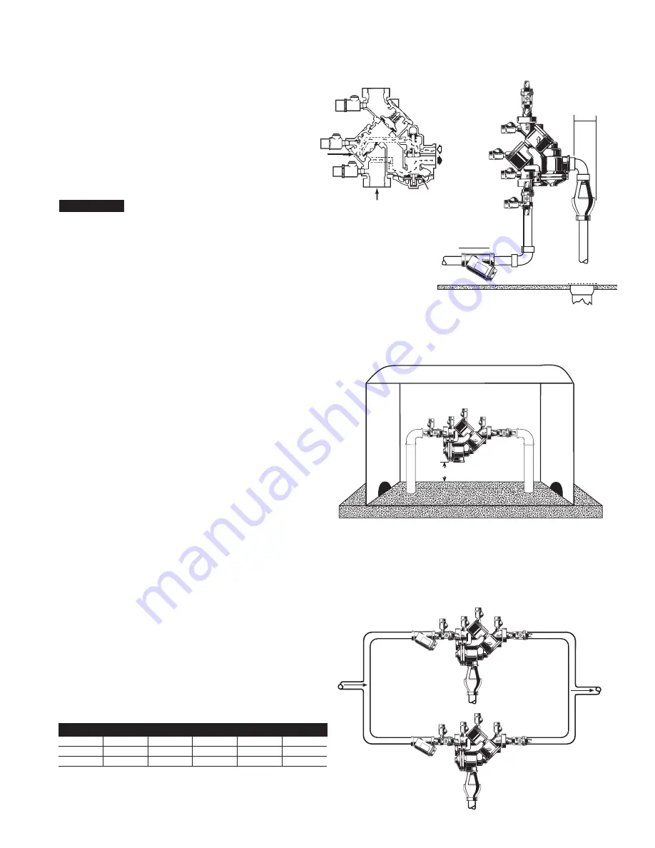
For indoor installations, it is important that the valve be
easily accessible to facilitate testing and servicing. Series
909 and LF909 may be installed either vertically or hori-
zontally. If it is located in a line close to wall, be sure the
test cocks are easily accessible. A drain line and air gap
should be piped from the relief valve connection as shown,
where evidence of discharge will be clearly visible and so
that water damage will not occur. Therefore, never install
in concealed locations.
NOTICE
Test cock must be located on the first or inlet shutoff
valve.
Flow
Relief Valve
Below First Check
Valve
Air In
Water
Out
Main
▼
Min.
4
1
⁄
2
"
▼
▼
Air*
Gap
First
Check
Valve
909QT-S/
LF909QT-S
Vertical Installation - Upward Flow
*For Air Gap information contact your technical
sales representative or refer to ES-AG/EL/TC.
In an area where freezing conditions do not occur, Series 909/LF909
can be installed outside of a building. The most satisfactory installa-
tion is above ground and should be installed in this manner when-
ever possible.
In an area where freezing conditions can occur, Series 909/LF909
should be installed above ground in an insulated enclosure.
Series 909/LF909 may be installed in a vertical or horizontal line
and in an accessible location to facilitate testing and servicing. A
discharge line should be piped from the air gap at the relief valve
connection making sure there is adequate drainage. Never pipe the
discharge line directly into a drainage ditch, sewer or sump. Series
909 and Series LF909 should never be installed where any part of
the unit could become submerged in standing water. Consideration
should be given to the installation of external support structure as
applicable.
It is generally recommended that backflow preventers never be
placed in pits unless absolutely necessary, and then only, when
approved by local codes. In such cases, a modified pit installation is
preferred.
Two or more smaller size valves can be piped in parallel (when
approved) to serve a larger supply pipe main. This type of installation
is employed where increased capacity is needed beyond that provid-
ed by a single valve and permits testing or servicing of an individual
valve without shutting down the complete line.
The number of valves used in parallel should be determined by the
engineer’s judgement based on the operating conditions of a specific
installation.
Installation Indoors
Installation - Outside Building Above Ground
Installation - Parallel Consult Local Codes for Approval
909QT-S/LF909S
909QT-S/LF909QT-S
Air Gap
(Drawings not to scale)
TABLE ONE - CAPACITY REQUIRED FOR SYSTEM
50 gpm
100 gpm
150 gpm
200 gpm
250 gpm
350 gpm
Two
3
⁄
4
"
Two 1"
Two 1
1
⁄
4
"
Two 1
1
⁄
2
"
Two 1
1
⁄
2
"
Two 2"
Devices
Devices
Devices
Devices
Devices
Devices
Table shows total capacity provided with dual valve installations of various sizes.


