USER MANUAL & INSTALLATION GUIDE
B
LÜCHER
®
Connected Roof
SIPHONIC
ROOF
GREEN
BLUE
GRAVITY
INTELLIGENT
BALCONY
& PARKING
REV. 01 / OCTOBER 2020
Page 1: ...USER MANUAL INSTALLATION GUIDE BLÜCHER Connected Roof C INTELLIGENT ROOF BALCONY PARKING REV 01 OCTOBER 2020 ...
Page 2: ...ay 14 7 1 1 Menu structure 14 7 1 2 Menu content 15 7 1 3 Display information 16 7 2 Info button 16 7 3 Relay 17 7 4 Measurement values 18 7 4 1 Water Level 18 7 4 2 Temperature 18 7 5 Diagnostics 18 7 5 1 Offset 18 7 5 2 Systems Diagnostics 20 7 6 Monitor modes 20 7 6 1 Operation Mode 20 7 6 2 Test Mode 20 7 7 Power up reboot 20 8 Modbus interface 21 8 1 Supported function codes 21 8 2 Modbus Ter...
Page 3: ...eways must be installed if you have more than 16 Monitors in the system You can set the system up in different ways to receive the information 1 The information can be read directly on the Gateway display 2 You can use the relay output to trigger a visual or an acoustic alarm 3 You can use the Modbus signal to communicate directly with the Building Management System BMS 4 You can apply a GSM gatew...
Page 4: ...ed instructions 1 Optional accessories Item Description External antenna 868 MHz SMA connection w 3 m cable Must to be ordered separately item number 900 900 000 3 Safety instructions and regulations Installation must be suitable for the on site conditions and comply with the local regulations and technical rules Please note that alterations or improper repairs to the product are not permitted If ...
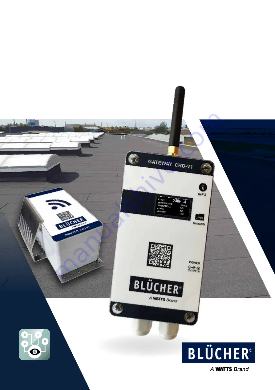
Page 5: ...specification 4 1 Product overview GATEWAY 1 Antenna 2 Info button 3 SD card 4 Input for power supply 5 Relay output 6 Internal power supply 7 Modbus 8 Jumper switch MONITOR 9 Mounting bracket 10 Level sensor 11 Monitor ID 1 2 3 4 223 mm 80 mm 5 6 7 8 10 11 9 ...
Page 6: ... MicroSDHC Class 4 or higher Size 4 GB Relay Type 1RT NO NC Load limit 230VAC 5A Connection 3 pin screw terminals Max 1 5mm MODBUS Physical Layer RS485 Baud rate Up to 115200 Bauds Connection 3 pin screw terminals Max 1 5mm Termination Yes ON OFF jumper configuration Cable glands Size PG7 diameter 2 5 6 5mm Enclosure IP protection IP 30 Material ABS Size 120 x 65 x 40mm without antenna and cable g...
Page 7: ...e recommend that the Gateway is placed centrally in relation to the Monitors and in line of sight to ensure the best possible signal strength Please note that obstructions such as concrete and metal can reduce the signal range Do not install the BLÜCHER Connected Roof Gateway in areas with a risk of water exposure and high humidity levels The ambient temperature should be in the range between 10 C...
Page 8: ...Ø4 mm and screws are not included Ensure there is enough free space around the unit to enable access to the SD card and to allow space for the antenna and cable glands If there is no room for the gateway because of the antenna or if the placement of the gateway will disturb the signal to the antenna an external can be an option Item number 900 900 000 The external has a magnetic socket and can be ...
Page 9: ...up Relay Relay can be wired as NO or NC Internal power As an alternative to the power connector on the right side of the Gateway a 5V DC power supply can be wired directly to the power terminals Modbus If connection to a Modbus RTU BMS system is required a suitable RS485 cable must be used and connected to A B GND If connection to a Modbus RTU BMS system is required a suitable RS485 cable must be ...
Page 10: ...ecommend that one Monitor is installed next to each drain on your roof Monitors should be installed at the primary drainage system and not at emergency outlets and drains This gives the system the best conditions to evaluate the performance of the drainage system ...
Page 11: ...e water levels on the Monitor in the config file see chapter 7 5 Before installing the Monitor ensure that the surrounding roof area and the bracket are cleaned carefully before application of the recommended glue sealer for the roof type 1 Clean Bracket 2 Clean Roof 3 Glue Use glue sealer recommended for you roof type 40 mm 60 mm Position the Monitor including bracket 40 60 mm from the edge of th...
Page 12: ...tor Test mode to reduce time see capture 7 6 7 Verify that there are no errors or warnings in the display 8 Verify Modbus values and functionality As an alternative to power OFF ON the Remove SD card mode can be entered by pressing the Info button for 5 seconds When the SD card is mounted again the Gateway will reboot and read the new configuration This step is only for setting up BMS systems 6 1 ...
Page 13: ...on the Monitor Label One Gateway supports up to 16 Monitors Omit all zeros 0 in front of monitor ID See label and configuration file examples below General Settings Optional Gateway system settings No changes needed Relay Settings Optional Only needed if the Relay function is needed Roof alarm setting Optinal To parameterized the sensitivity of Roof alarms BMS Settings Optional If Modbus RTU is us...
Page 14: ...vided into 3 sections start up waiting for data and operation During start up the Gateway software version can be read Every time the Gateway has been re booted it will wait up to 30 minutes until the first Monitor has been detected When the first Monitor has been detected the display will jump to operation and show the Data view By pressing the info button the next Monitor s data will be shown ...
Page 15: ...REV 01 OCTOBER 2020 BLÜCHER CONNECTED ROOF 15 7 1 2 Menu content ...
Page 16: ...nge for the near future 20 2 years 50 5 years 100 10 years Signal strength Signal too weak and will cause intermittent operation Low signal Distance obstructions on the limit High signal Temperature XX C Celsius degrees C Water level X 5 Level 1 5 Alarm YES NO IF YES alarm will be shown in the alarm list Version X XX Monitor software version 7 2 Info button The info button is used for performing s...
Page 17: ...Blocked sensor Low battery Lost connection Internal leak Temp One setpoint For application where only one setpoint is needed Temp Two setpoints For application where two setpoints are needed For more info on Alarm s see chapter 7 5 diagnostics The parameters for the Temp modes can be parametrized in the config file see Appendix 13 Appending on the application 1 or 2 set points can be selected see ...
Page 18: ...ated more frequently 7 5 Diagnostics There are two types of diagnostics Roof diagnostics and Monitor systems diagnostics See detail in chapter 7 5 1 and 7 5 2 7 5 1 Roof diagnostics The Gateway incorporates an algorithm that activates an alarm based on water level across all Monitors over time Two alarm conditions can be detected Roof Diagnostics Blocked drain Appears when a Monitor detects higher...
Page 19: ...TER BLOCKED_DRAIN_ALARM_SET_COUNTER Counter of incidents that activate an alarm BLOCKED_SENSOR_NOALARM_RESET_COUNTER BLOCKED_DRAIN_NOALARM_RESET_COUNTER Number of no incidents to set counter to 0 AUTOMATIC_ALARM_REMOVING Alarm removes automatic after time WATER_LEVEL_OFFSET_ID_1 0 WATER_LEVEL_OFFSET_ID_2 0 WATER_LEVEL_OFFSET_ID_3 0 WATER_LEVEL_OFFSET_ID_4 0 WATER_LEVEL_OFFSET_ID_5 0 WATER_LEVEL_OF...
Page 20: ...values diagnostics and system data are transmitted when measurement values change or at least every 30 minutes Out of the box the Monitor operates in OPERATION MODE ready to use and connect to a Gateway 7 6 2 Test Mode In TEST mode measurement values are sent every 3 minutes This mode is used to debug or speed up commissioning To enter TEST mode short circuit pin 0 and 1 for two seconds Successful...
Page 21: ...tion resistor is connected OFF Internal termination resistor is disconnected NB Power off before changing the jumper switch position 9 Gateway software update To install the new software follow these steps 1 Press the push button for 5 seconds this allows the SD card to be ejected 2 Copy the update file to the SD card 3 With the SD card reinstalled in the Gateway the Gateway will reboot and the ne...
Page 22: ...BER 2020 10 Service and maintenance We recommend regular service and maintenance around the area of a drain with a Monitor Dirt and other obstructions can affect the performance of your drainage system and the BLÜCHER Connected Roof system ...
Page 23: ...p Distance too far Wait up to 4 hours Check signal strength Move the Gateway closer to the Monitor Add external antenna Add additional Gateway Permanent connection loss Wrong ID in config file Distance too far Check Config file Move the Gateway closer to the Monitor Add external antenna Add additional Gateway Monitor battery issue Replace Monitor Defect Monitor Replace Monitor Expected alarm not s...
Page 24: ...eplace any defective Connected Roof Product in whole or in part according to BLÜCHER s General Terms and Conditions of Sale However the warranty does not cover device defects that result from abuse accident or misuse Also it does not cover uses that are not in accordance with the present User manual Installation Guide 2 Limit of Liability Product Disclaimer BLÜCHER s Connected Rooftop Product does...
Page 25: ...y setting 1 BLOCKED_SENSOR_LIMIT_FACTOR 1 to 255 Factory setting 20 BLOCKED_SENSOR_ALARM_SET_COUNTER 1 to 255 Factory setting 5 BLOCKED_SENSOR_NOALARM_RESET_ COUNTER 1 to 255 Factory setting 4 BLOCKED_DRAIN_LIMIT_FACTOR 1 to 255 Factory setting 20 BLOCKED_DRAIN_ALARM_SET_COUNTER 1 to 255 Factory setting 15 BLOCKED_DRAIN_NOALARM_RESET_COUNTER 1 to 255 Factory setting 4 BMS settings BMS_SLAVE_ADDRES...
Page 26: ...nt16 decimal place 2 0 100 00 00131 humidity max 32 uint16 decimal place 2 0 100 00 00132 battery level 33 uint16 decimal place 2 0 100 00 00133 communication signal level 34 uint16 decimal place 2 0 100 00 00134 diagnostic sensor signal 35 uint16 0 40 00135 diagnostic internal leak 36 uint16 0 255 00136 diagnostic water level 1 37 uint16 0 255 00137 diagnostic water level 2 38 uint16 0 255 00138 ...
Page 27: ... octet 12431 8 15 hex 2nd octet 12431 0 7 hex 3rd octet 12432 8 15 hex 4th octet 12432 0 7 1 HW version2 1 uint8 A 0 256 12501 8 15 uint8 B 0 256 12501 0 7 16 HW version2 16 uint8 A 0 256 12516 8 15 uint8 B 0 256 12516 0 7 1 SW version2 1 uint8 A 0 256 12601 uint8 B 0 256 12601 16 SW version2 16 uint8 A 0 256 12616 8 15 uint8 B 0 256 12616 0 7 1 frame counter 1 uint32 big endian byte order 12701 1...
Page 28: ...ed sensor alarm Monitor 11 bool 12952 10 Blocked sensor alarm Monitor 12 bool 12952 11 Blocked sensor alarm Monitor 13 bool 12952 12 Blocked sensor alarm Monitor 14 bool 12952 13 Blocked sensor alarm Monitor 15 bool 12952 14 Blocked sensor alarm Monitor 16 bool 12952 15 1 st Blocked drain Alarm Monitor ID uint16 12953 1 st Blocked sensor Alarm Monitor ID uint16 12954 1 water level 1 uint8 0 5 1300...
Page 29: ...V 14616 0 7 1 diagnostic battery voltage min 1 uint8 x20 and decimal place 3 0 4 000 V 14701 0 7 16 diagnostic battery voltage min 16 uint8 x20 and decimal place 3 0 4 000 V 14716 0 7 1 diagnostic error counter 1 uint16 14801 16 diagnostic error counter 16 uint16 14816 1 diagnostic CTN temperature 1 uint16 35 0 85 0 C 14901 16 diagnostic CTN temperature 16 uint16 35 0 85 0 C 14916 1 clear communic...
Page 30: ... number of configured sensors 05 uint8 0 99 00005 0 7 gateway tag 06 string of 32 ASCII characters 1st character 00006 8 15 2nd character 00006 0 7 31st character 00021 8 15 32nd character 00021 0 7 relay mode 22 uint4 0 Temp mode 1 Alarm mode 00022 0 3 relay state bool 0 Relay is opened 1 Relay is closed 00022 4 sync time 31 uint32 UNIX Epoch time seconds 10 digit holding register R W 16 00031 00...
Page 31: ...REV 01 OCTOBER 2020 BLÜCHER CONNECTED ROOF 31 ...
Page 32: ...BALCONY PARKING 2020 blucher com T 45 99 92 08 00 blucher com BLÜCHER 04 MAINTENANCE 0 5 S U S T A I N A B I L I T Y 0 1 S P ECIFICATION 02 INSTALL A T I O N 0 3 U S E O P E R A T I O N 100 recyclable BIM CAD Dimensioning software Easy to handle Light weight Fast and easy installation Push fit no welding High flow rate Fire resistant Corrosion resistant No costs in building lifetime BLÜCHER Drain ...