Watex WATEX CMS-8 Installation And Operation Manual Download Page 8


WATEX Ltd., Latvia, Riga, Ganibu dambis 27 k-5

[email protected]

, Tel. +371 67381989, www.watex.eu 


INSTALLATION 

General conditions 

The softener must be placed on the flat, leveled surface. 
It is recommended to install the softener in the technical room with sound absorbing, because during the regeneration (usually at 
night), the flow of water to the sewers could be heard. 
 The control valve and connection fittings are not intended for supporting the weight of the water supply system. 
All sanitary-technical works to be performed in accordance with local plumbing and electrical codes. 
Filter must be provided with a continuous supply of water, which does not differ in quality  and quality within 30% and has the 
pressure range of 2.0 to 3.5 bar. 
The distance between the drain and the water conditioner should be as short as possible. 
The room temperature must not be lower than + 5 °C and not higher than 45 °C. 
Do not use for the filter connections petroleum jelly, oils, hydrocarbon lubricants or spray silicone. Silicon grease can be used on 
black o-type sealing rings, but it is not necessary. 
Nuts and bolts have been designed so they can be unscrewed or tightened by hand or special plastic key. If you need to unscrew 
the tightened nuts or couplings, you can use pliers. However, take care not to damage the plastic parts. Do not use wrenches or 
socket wrenches to tighten or loosen. 
Do not place the screwdriver into sleeve/cap openings and do not strike with a hammer! 
Teflon tape is not necessary for sewer and reagent connection fittings. 
Place the water filter so that the distance between the drainage outlet and the filter is minimized. 
Perform a general preventive maintenance at least once a year. 

Water pipe connection 

In  the rear  of  the  water  filter is  the  water  supply  connection.  Each  connection  has 
the inflow and outflow indicating arrows. If you look at the filter from the front, on 
the right side is the inflow and on the left side is discharge. The filter’s connection 
to the mains outer thread size 1 '' (inch), of  both input and output. Plastic threaded 
fitting  is  of  a  screw  type  and  it  can  freely  rotate  the  ring,  keeping  the  density. 
Therefore,  there  is  no need  for  very  powerful  (sufficient hand  strength)  tightening 
of the bolts on the control valve housing. 
Use of Teflon tape on the plastic threads is a must. 
The  material of  the  piping,  which  connects  to  the  filter,  does  not  make  significant 
difference.  Most  important  is  that  the  filter  does  not  bear  the  weight  of  the  water 
supply system. 
Filter  can  be  connected  with the  cast  iron, glued,  PVC  screw-fastening pipes.  It  is 

also possible with flexible metal pipes, soldered brass pipes. 

 
Note:
 soldering of pipes must be carried out before connection to the control valve plastic fittings failing to follow this rule can 
result in internal damage of the plastic fittings and they will not provide consistency of connection. 
Soldering fittings must be cooled down. Avoid soldering grease contact with any connecting fitting parts. 


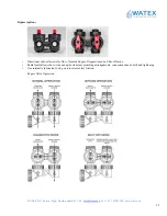
For the water filter, it is recommended to install a bypass valve, as shown in the figure, and sample valves before inflow and 
outflow as well. 
During the normal operation, bypass valve is closed, but the input and an output valves are open. 
During the preventive maintenance works on the installation or filter repair, the not purified water can be supplied to the 
consumers. 
It is recommended to install the sampling valve before and after the filter to compare /determine the quality of raw water and the 
just-  purified  water.  It  is  also  advisable  to  install  pressure  gauges  before  and  after  the  filter  to  control  the  pressure  loss  in  the 
installation. 
In order to enhance the durability of the filter first it is recommended to install a mechanical filter that prevents sand particles, 
which can be lifted out of the hole and to lead to clogging the parts of the filter. 


Summary of Contents for WATEX CMS-8

Page 1: ...info watex eu Tel 371 67381989 www watex eu Installation and operation manual WATEX CMS 8 9 10 12 13 14 WATER SOFTENER Read the instructions carefully before use Watch CMS water softener start up vide...

Page 2: ...a Ganibu dambis 27 k 5 info watex eu Tel 371 67381989 www watex eu 2 CONTENTS INTRODUCTION 3 REQUIREMENTS 3 SPECIFICATIONS 4 SYSTEM MAIN COMPONENTS 5 OPERATION MODES 7 INSTALLATION 8 START UP 15 PROBL...

Page 3: ...another person using your hands Moving by hands it is recommended to grab the top behind the control valve housing the place where the control valve connects to the tank and the bottom behind the blue...

Page 4: ...Width m 0 28 0 28 0 28 0 3 0 46 0 46 Height m 1 14 1 47 1 62 1 57 1 62 1 91 Weight filled with water kg 50 60 70 95 155 195 Connection in out drain inches 1 1 3 4 1 1 1 Clack control unit WSCI 1 WS CI...

Page 5: ...atvia Riga Ganibu dambis 27 k 5 info watex eu Tel 371 67381989 www watex eu 5 SYSTEM MAIN COMPONENTS The softener has three main basic components resin tank Clack control valve and brine tank 2 1 1 Co...

Page 6: ...ufficient to dissolve part of the NaCl regeneration cycle Brine well The brine well is a cylindrical barrier that keeps the salt or potassium chloride away from the safety float and air check valve wh...

Page 7: ...s the resin and large amounts of sodium ions replace the hardness ions accumulated during service 3 Second backwash After brine is completely removed from the brine tank into the resin tank the brine...

Page 8: ...indicating arrows If you look at the filter from the front on the right side is the inflow and on the left side is discharge The filter s connection to the mains outer thread size 1 inch of both input...

Page 9: ...rinsing is not dropping out Secure it Important Make sure the garden hose is not folded because it will reduce rinsing water flow and the filter is likely to have incomplete rinsing which can lead to...

Page 10: ...trol panel is shown in the drawing highlighting the connection point of the reagent supply line The pipeline connection is carried out as follows 1 Unlock the control unit reagent by removing the clam...

Page 11: ...ypass option Directional shut off arrows for flow Normal Bypass Diagnostic mode Shut off mode Radial seals allow side to side and up down minor plumbing misalignments connections need only hand tighte...

Page 12: ...To ensure a continuous supply of electricity from the source located not farther than 2 meters from the water softener Adapter wire must be connected inside the control valve 1 Remove the front cover...

Page 13: ...s made while in programming modes Toggles between available User Display Screens or Allows programmer to advance to the next display screen in programming mode Change variable being displayed in progr...

Page 14: ...WATEX Ltd Latvia Riga Ganibu dambis 27 k 5 info watex eu Tel 371 67381989 www watex eu 14 Setting Time of Day Installer Display Settings...

Page 15: ...iously set data is automatically saved and the programming progresses to the next settings Next press NEXT until the current day is displayed Therefore the setup cycle is closed and all settings are s...

Page 16: ...peration control During operation the normal user display is time of day current flow rate liters per minute remaining capacity cubic meters per hour Each of these can be viewed by pressing NEXT to sc...

Page 17: ...E3 Motor runs too long out of adjustment trying to reach the next regeneration cycle position 1004 Motor runs too long out of adjustment trying to reach the starting position If some other code shows...

Page 18: ...ntrol valve does not make recovery automatically but it does so when REGEN button is pressed a Water flowing through the bypass a Close the bypass b the meter is disconnected b Connect the meter to th...

Reviews: