background image

54

Recommended Preparation Procedures

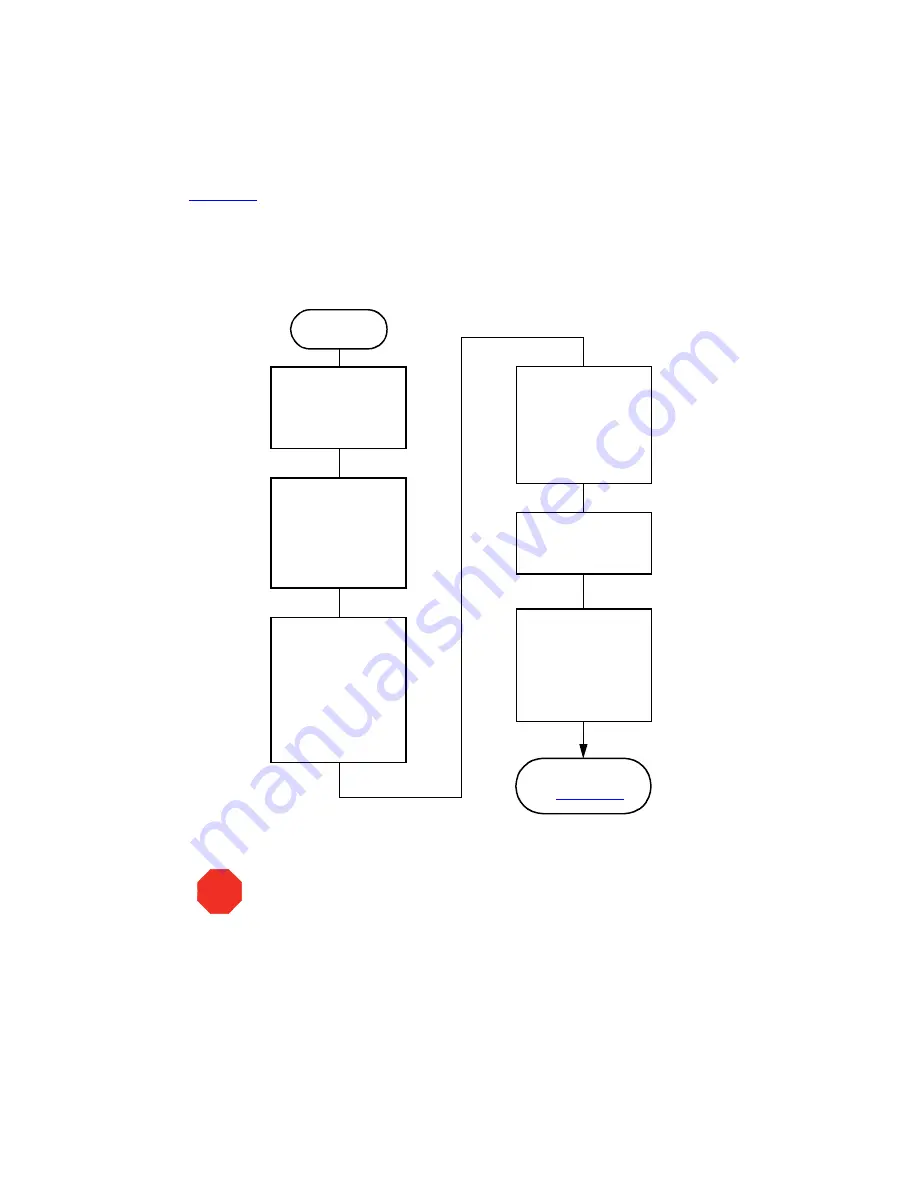
Figure 6-5

 outlines how to change from a buffered solvent to a totally organic solvent in a 

sparge-based Separations Module.

Note:

 All flow chart references refer to sections or figures in the Waters 2690 Separations 

Module Operator’s Guide.

Figure 6-5  Changing from a Buffered Solvent to an Organic Solvent

(Sparge-Based Separations Module)

Remove the Solvent 

Line from the 

Reservoir Containing 

the Buffered Solvent

Purge the Injector 

for a Minimum of 6 

Loop Volumes 

(See “Purging the 

Injector” in 

Section 4.4.2)

Using a Flow Rate of 

2.000

 mL/min, 

Perform a Wet Prime 

Until Air Begins to 

Enter the Line 

(See Section 4.4.2)

Fill a Clean Solvent 

Reservoir with the 

Organic Solvent and 

Place the Solvent 

Line in

the Reservoir

Start

Place the Previously 

Removed Solvent 

Line into Filtered 

HPLC-Grade Water 

and Perform a Wet 

Prime for 

2

 min at

5

 mL/min 

(See Section 4.4.2)

Perform the Steps 

in 

Figure 6-1

Remove the Solvent 

Line from the 

HPLC-Grade Water

STOP

Attention:


To avoid having salts precipitate in the Separations Module, use an 

intermediate solvent such as water when you change from buffers to 
high-organic-content solvents. Refer to Section D.3, Solvent Miscibility, for 
information on solvent miscibility

Summary of Contents for 2690

Page 1: ...Waters 2690 Separations Module Quick Start Guide 34 Maple Street Milford MA 01757 WAT553 03TP Revision 3...

Page 2: ...f publication In no event shall Waters Corporation be liable for incidental or consequential damages in connection with or arising from the use of this manual 1996 1998 2000 WATERS CORPORATION PRINTED...

Page 3: ...Management System Adjust the Seal Pack Prime the Needle Wash Pump Load the Carousels Yes No Perform an Automatic Run Set Control Switches Set Flow Rate and Composition Set Sparge Rate if Applicable P...

Page 4: ...is important to the operator For example Note Record your result before you proceed to the next step Attentions provide information about preventing possible damage to the system or equipment For exam...

Page 5: ...u chemistry and does not contain background or reference information For additional information or if you want to learn how to modify any of the procedures in this guide refer to the Waters 2690 Separ...

Page 6: ...figurations differing from each other by the options that are included The two primary configurations are designated 2690 Provides quaternary solvent high performance solvent delivery integral helium...

Page 7: ...begins 2 1 Powering On Startup Diagnostics The startup diagnostics routine performs the following functions and tests CPU board Memory RAM and ROM Keypad Display External communication Digital signal...

Page 8: ...lves Carousel carrier Solvent management system The statuses of these mechanical diagnostics tests appear in the banner area of the Main screen Figure 2 2 while the diagnostics are running If the star...

Page 9: ...atography Manager workstation and operate the Separations Module and the other HPLC system components from their front panels To set the Separations Module to the No Interaction mode 1 Press the Confi...

Page 10: ...In this remote control mode a Millennium Chromatography Manager workstation running Millennium 32 software Windows 95 98 or NT controls the operation of your HPLC system using the IEEE 488 interface b...

Page 11: ...e controlled from the MassLynx computer Controlled by Millennium 2 xx Mode In this remote control mode a Millennium Chromatography Manager workstation running Millennium 2 xx software Windows 3 1 cont...

Page 12: ...Events In discussion Section 3 2 1 Setting Configuration Parameters 4 Set the Stop Flow field to the appropriate condition Ignore High or Low then press Enter Choose Ignore if the Stop Flow I O termi...

Page 13: ...ons Module to the Controlled via RS 232 ASCII or Binary mode 1 Select the System field in the Configuration screen then press Enter to display a list of choices 2 Select Controlled via RS232 ASCII or...

Page 14: ...ed tables Misc parameters Generates a list of all parameters not included in tables System config Generates a list of the instrument configuration parameters Per inject data Generates a list of the mi...

Page 15: ...ecified period of inactivity Use the auto shutdown function When there is a long delay between injections To minimize solvent flow after an unattended or long run To minimize sparge gas consumption To...

Page 16: ...e Separations Module shuts down when there has been no activity for the specified period 6 Press Exit to return to the Main screen Note If you want to use Auto Shutdown to turn off the lamp of a 2487...

Page 17: ...r Operation 2 3 1 Degassing Solvents In Line Vacuum Degassing In line vacuum degassing reduces the total dissolved gas in the mobile phase For more information on vacuum degassing refer to Section 1 5...

Page 18: ...the in line vacuum degasser from the Status screen 1 Press the Menu Status key The Status screen appears as shown in Figure 2 7 The content and layout of the Status screen varies with the options ins...

Page 19: ...appears Figure 2 8 Figure 2 8 Programmed Sparge Dialog Box 3 In the Time field enter the time to run the initial sparge cycle then enter values for each solvent reservoir for the following parameters...

Page 20: ...appropriate reservoir s Be sure the detector waste line and the sample loop waste line drain into an appropriate container 3 Gently shake the filters in the reservoirs to remove any bubbles that may b...

Page 21: ...h solvent line you want to prime then close the prime vent valve 10 Press a screen key corresponding to the solvent line with which you want to prime the system Waters recommends that you prime using...

Page 22: ...elp purge air from the lines especially if the in line vacuum degasser is installed 2 Press the Direct Function screen key in the Status screen The Direct Functions menu appears Figure 3 4 3 Select th...

Page 23: ...Functions menu appears Figure 3 4 4 Select Wet Prime then press Enter The Wet Prime dialog box appears Figure 2 11 5 Enter a flow rate of 0 000 mL min and a time of 5 min At the end of the time period...

Page 24: ...t tube 5 Press the Prime SealWsh screen key then press the Start screen key The seal wash procedure begins Push on the syringe plunger to force seal wash solvent through the system 6 When seal wash so...

Page 25: ...rations Module at the beginning of each day To purge the sample management system 1 In the Main screen press the Menu Status key to display the Status screen Figure 2 7 2 Enter the appropriate solvent...

Page 26: ...flush the sample loop with the selected volume 6 Leave the Compression Check check box blank the first time you start up the system to prevent a compression test from occurring The Separations Module...

Page 27: ...screen key in the Main screen The Diagnostics screen appears Figure 2 12 3 Press the Prime NdlWsh screen key The 30 second needle wash procedure begins If solvent does not flow out of the waste tube w...

Page 28: ...n the dialog box that appears 2 4 4 Loading Carousels Loading carousels involves Loading the vials into the carousel Loading the carousel into the sample compartment Loading Vials Use only 12 32 mm 2...

Page 29: ...able for loading the appropriate carousel 3 Load the carousel into the sample compartment 4 Repeat steps 2and 3 until all appropriate carousels are loaded 5 Close the carousel door If you enable the V...

Page 30: ...You perform direct control runs from the Status screen Figure 3 2 and Figure 3 3 The fields in the Status screen indicate the status or values of the current operating parameters as described in Tabl...

Page 31: ...rforming a Direct Control Run 31 Figure 3 2 First Page of Status Screen Press the Next Page screen key to display the second page of the Status screen Figure 3 3 Figure 3 3 Second Page of Status Scree...

Page 32: ...ent switches on the I O connector Degasser Mode Vac pump Pressure Indicates the status of the in line vacuum degasser if installed Selects the mode of operation Normal Continuous or Disable Indicates...

Page 33: ...of the column if the column heater is installed Injector Indicates the current position of the injector Valid positions are Stream In the high pressure stream Seal In the lower seal position Wet In th...

Page 34: ...want to specify press the number beside the function or use the arrow keys then press Enter Follow the instructions for each function Figure 3 4 Direct Functions Menu 2410 and 410 Cell Col 1 Col 2 In...

Page 35: ...mobile phase As an option performs a compression test Purge 2410 410 Reference if applicable Purges the Waters 2410 or 410 RI detector reference cell Program Sparge if applicable Sets the sparge rate...

Page 36: ...Sets and Templates for information on creating and editing separation methods sample sets and sample templates Controlled By Millennium Chromatography Manager Modes If your HPLC system is controlled...

Page 37: ...ing an Automatic Run in a Stand Alone Configuration Press the Run Samples Screen Key on the Main Screen Enter Information Required by the Separation Method Sample Set or Sample Template Press the Run...

Page 38: ...de 1 Press the Run Samples screen key in the Main screen Figure 2 2 The Run Samples screen appears Figure 4 2 Table 4 3 describes the icons used in the Run Samples screen Figure 4 2 Run Samples Screen...

Page 39: ...ys the selected sample set table to view or edit as shown in Figure 4 3 Use the screen keys to modify the table as necessary Figure 4 3 Sample Set Screen Functional View 4 Load the sample vials into t...

Page 40: ...ion at the end of this section You can perform an automated run in a stand alone mode using a sample template stored in the Separations Module Screen prompts give you step by step directions to prepar...

Page 41: ...n press the Continue screen key You must use consecutive standard vials 8 Make sure that the solvents listed in the dialog box are primed and in the appropriate inlet tubes then press the Start screen...

Page 42: ...the current injection the current injection is not affected by the changes You must save the changes to the modified separation method before you can apply the method to all subsequent injections tha...

Page 43: ...e existing method An error message appears if you attempt to transfer more than 60 methods into the Separations Module Exporting Methods To export one or more separation methods sample sets or sample...

Page 44: ...Export Methods Screen 4 Select the method you want to export to the disk then press Select Method To select an additional method select the method desired then press Select Method again To select all...

Page 45: ...ludes the 2690 solvent management system and the sample management system Refer to the Millennium documentation for information on creating a chromatographic system For Millennium32 software create a...

Page 46: ...software When the Separations Module is running under MassLynx control the word Remote appears in the banner area Making an Automatic Run Using MassLynx Software To make an automatic run perform the f...

Page 47: ...e set Hold Gradient screen key Holds the current gradient conditions A screen key allows you to resume the gradient Stop Flow on the keypad Stops the flow of solvent suspends operation of the current...

Page 48: ...resh solution of 80 water 20 methanol or a miscible solvent and prime the plunger seal wash pump see Section 2 3 2 Priming the Solvent Management System the Priming the Plunger Seal Wash Pump discussi...

Page 49: ...or dry Separations Module A Separations Module that has been turned off or left idle with no flow A Separations Module that requires a solvent change such as from a buffered solvent to an organic sol...

Page 50: ...eservoirs at an Initial Sparge Rate of 100 for at Least 15 min Set an Idle Sparge Rate of 30 to 50 See Section 4 4 4 Equilibrate for a Minimum of 10 Column Volumes See Section 4 4 5 Purge the Injector...

Page 51: ...olvents for 10 min at 5 00 mL min See Section 4 4 2 Repeat the Wet Prime at the Same Rate and Time for Each Solvent To Make a Gradient Run for Example A B Set the A and B Composition Fields in the Sta...

Page 52: ...Degassed by Vacuum Filtration See Section 2 6 3 Sparge all Reservoirs at an Initial Sparge Rate of 100 for at Least 15 min Set an Idle Sparge Rate of 30 to 50 See Section 4 4 4 Equilibrate for a Mini...

Page 53: ...njector in Section 4 4 2 Perform a Wet Prime for One of the Solvents for 2 min at 7 500 mL min See Section 4 4 2 Repeat the Wet Prime at the Same Rate and Time for Each Solvent If You Want to Make a G...

Page 54: ...Injector in Section 4 4 2 Using a Flow Rate of 2 000 mL min Perform a Wet Prime Until Air Begins to Enter the Line See Section 4 4 2 Fill a Clean Solvent Reservoir with the Organic Solvent and Place t...

Page 55: ...Clean Solvent Reservoir with the Organic Solvent and Place the Solvent Line in the Reservoir Start Place the Previously Removed Solvent Line into Filtered HPLC Grade Water and Perform a Wet Prime for...

Reviews: