


1
2
QS3200 User’s Manual
Page 12
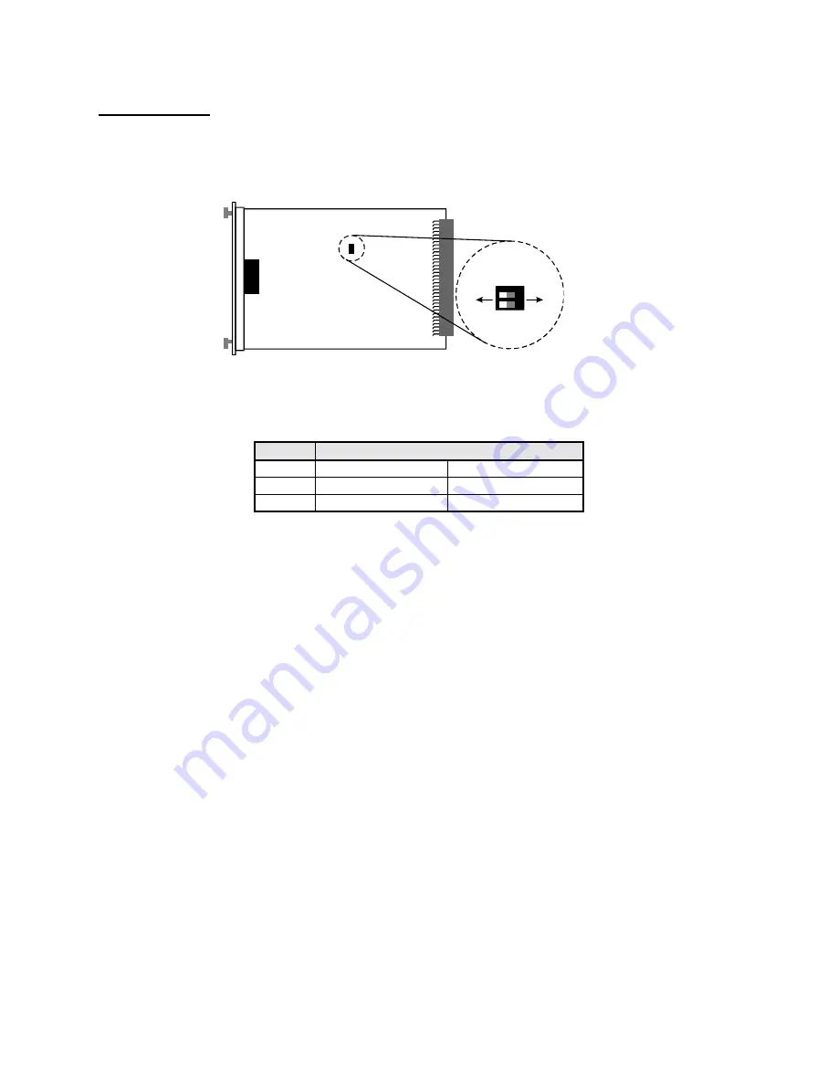
1000Base Modules
On the 1000Base modules, if the dip switch is set to
OFF
, N-Way is enabled. Full and half duplex cannot be
enabled if auto-negotiation is in use. If auto-negotiation is disabled, the DIP switch for half and full duplex is
enabled.
Figure 7 – Dip Switch Location for the Module PM-1G-MMSX or SMLX (1000Base-SX or LX fiber module
Table 3 lists the port operating modes based on the dip switch position.
Gigabit Port
SW 1
2
ON
Disable N-way
Half Duplex
OFF
Enable N-way
Full Duplex
Table 3 - Dip Switch Settings for the 1000Base-SX/LX Fiber Module
5.0 Troubleshooting
All Waters’ switching products are designed to provide reliability and consistently high performance in all network
environments. The installation of Waters’ QS3200 switch is a straightforward procedure (See Section 3)
;
the
operation is
also straightforward and is discussed in Section 4.
Should problems develop during installation or operation, this section is intended to help locate, identify and correct
these types of problems. Please follow the suggestions listed below prior to contacting your supplier. However, if
you are unsure of the procedures described in this section or if the Waters’ QS3200 switch is not performing as
expected, do not attempt to repair the unit; instead contact your supplier for assistance or contact Waters Network
Systems’ Customer Support Center at
800.328.2275
or email [email protected].
5.1
Before Calling for Assistance
1. If difficulty is encountered when installing or operating the unit, refer back to the Installation Section of the
chapter of this manual. Also check to make sure that the various components of the network are inter-operable.
2. Check the cables and connectors to ensure that they have been properly connected and the cables/wires have
not been crimped or in some way impaired during installation. (About 90% of network downtime can be
attributed to wiring and connector problems.)
3. Make sure that an AC power cord is properly attached to the QS3200.
4. Be certain that each AC power cord is plugged into a functioning electrical outlet. Use the PWR LEDs to verify
each unit is receiving power.
5. If the problem is isolated to a network device other than the Waters’ QS3200 switch, it is recommended that the
problem device be replaced with a known good device. Verify whether or not the problem is corrected. If not,
DIP Sw itch Location
Fu
ll
D
u
pl
e
x
En
a
b
le
N-
w
a
y
Di
s
a
b
le
N-
w
a
y
Ha
lf
Du
p
le
x
DIP
2
DI
P
1
2
1
ON
OF
F


