Waterous CP-1 Series Overhaul Instructions Download Page 21

F-1031, Section 4205.1

Page 20 of 24

Rev: 01/18/08

Keep the hub diameters within 0.015 in. TIR of the impeller shaft bore. If the
impeller hubs do not clean up at first undersize dimension, turn the hub down
to the next degree of undersize. Replace the impeller if the hubs do not clean
up at the last undersize dimension.

Before pressing new wear rings in place, remove all corrosion from body and
head counterbores and apply a generous amount of lubriplate or similar lubri‐
cant to the outer ring surfaces. With a suitable arbor, carefully press the rings
into the body and head counterbores. Make sure the rings are seated firmly
against the counterbore shoulders.

Reassembly

Reassembly of the CP- 1, CP- 2, CP- 2L and CPD- 2 pumps are essentially the
same as the disassembly procedure, except it is reversed. NOTE that if under‐
size wear rings are required, they should be installed during reassembly. Also, if
a new impeller is needed, install new standard size wear rings for the impeller.

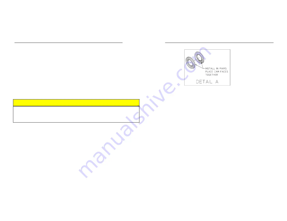
NOTE: If using a Nord- Lock

R

 washer, see Detail A for proper assembly.

NOTE: Apply Loctite

R

 242 to shaft and nut threads. Tighten impeller nut

until seated against impeller. Do not torque over 75 ft.-lbs (102 N.m).

Mechanical Seal

Install the mechanical seal as follows (See Figure 15 on the next page for different mechanical seal designs):

CAUTION

The mechanical seal primary and stationary rings are made of brittle materi‐
al. The material can be cracked or chipped. Extra care must be taken when
handling these rings.

NOTE: If Waterous Mechanical Seal Lubricant part no. 52608 is not avail‐
able, P80 rubber lubricant, straight dish soap or glycerin may be substi‐
tuted.

1.

Apply a light coating of seal lubricant to the rubber seat ring or o-ring on
the stationary ring assembly.

NOTE: To protect the rubber bellows of the mechanical seal, place a
piece of masking tape over the keyway on the impeller shaft, making
sure that the tape is able to be removed after bellows has passed
over the keyway.

2.

Protect sealing surface and press assembly squarely into bore of pump
head until it is seated. Ensure sealing surface faces primary ring. See the
following page for proper stationary ring orientation.

3.

CP-1 and CP-2 only (Pre 1/1/98 pumps only): Check the stationary ring
assembly to make sure the rubber seat ring is tight on the metal seat. Also
make sure rounded corner (side with identification dot) of seat ring faces
away from the shoulder of the stationary ring.

NOTE: For CP-1 and CP-2 (Pre 1/1/98) only: If mechanical seal sta‐
tionary ring assembly will not enter the pump head under finger

pressure, install only the rubber seat ring in the pump head. Using
finger pressure, the stationary ring can then be installed in the seat
ring.

4.

Wipe seal surface with denatured alcohol and a clean cloth.

NOTE: It is very important to keep the sealing surfaces clean. Dirt
and oil on the sealing surfaces will prevent a good seal and can
cause premature wear.

5.

Slide pump head over the impeller shaft.

6.

Secure with bolts, hex nuts, screws and lock washers.

7.

Lubricate impeller shaft with mechanical seal lubricant.

8.

Ensure that primary ring is retained in the bellows assembly. (If the ring is
loose use a small amount of grease between the ring and bellows assem‐
bly as needed).

9.

Apply light coating of seal lubricant to the inside of bellows assembly.

10. Press assembled bellows and primary ring tightly against the stationary

ring assembly.

NOTE: To press the bellows assembly on the shaft, use a smooth
sleeve with an inner diameter of approximately 1-3/32 in. Make sure
the sleeve applies pressure only to the bellows and inner rings.

11.

(Pumps built prior to 2/4/05 only)

 Slide the spring and spring sleeve

over the end of the impeller shaft so the small end of the spring fits over
the shell of the bellows assembly.

12. Install the retaining ring.

Summary of Contents for CP-1 Series

Page 1: ...r Shaft 8 CP 2L Pumps 9 Removal of Volute Body from Pump Head 10 Removal of Impeller 11 Removal of Mechanical Seal 12 Removal of Impeller Shaft 12 CPD 2 Pumps 13 Removal of Volute Body from Pump Head 14 Removal of Impeller 15 Removal of Mechanical Seal 16 Removal of Impeller Shaft 17 Disassembly of Impeller Shaft Assembly 18 Inspection and Repair 19 Mechanical Seal 19 Impellers 19 Installing Under...

Page 2: ...ure to open at least one discharge valve slight ly to prevent the pump from overheating If the pump runs for a few minutes completely closed it may heat the water enough to scald someone when the valve is opened Overheating can damage the packing seals and other pump parts If the apparatus builder has installed a by pass system or other provi sion designed to prevent overheating opening a discharg...

Page 3: ...s 4 A suitable hoist and slings 5 Torque capability up to 325 lb ft While no special tools and equipment are required a few special items are illustrated or described so the mechanic can make them or they are available from the apparatus manufacturer or the Waterous Company These special items are not absolutely necessary but they will make the mechanic s work much easier Preliminary Testing Befor...

Page 4: ...When mounting these bearings on shafts always apply force to the inner races When bear ings have a tight fit in the housings and a heavy force is necessary to install them be sure to apply force only to the outer bearing races For either type of fit applying force to the wrong bearing race may damage the balls and race Installing Body Gaskets To provide added sealing for gaskets between body halve...

Page 5: ...Impeller Nut Impeller Retaining Ring Impeller Shaft Gasket Bolts Washers Nuts attaching Pump Head to Transmission Impeller Washer or Nord Lock R Washer Square Key Spring Sleeve Prior 2 4 05 Mechanical Seal Prior to 2 4 05 Hex Hd Screws Copper Washers attaching Pump Head to Volute Body Transmission Mounting Flange Pump Head Rear Wear Ring Packing Gland Washers Nuts Pumps with Packing Only Figure 1 ...

Page 6: ...screws nylok are used on pumps with bronze bodies 2 Separate the pump head from the volute body 3 Remove and discard the gasket NOTE The wear rings will remain in the volute body and pump head Removing the wear rings from the body or head is necessary only if they are damaged or badly worn See page 19 Figure 2 Volute Body Removal from Pump Head Volute Body Gasket Copper Washer Hex Hd Screw 7 16 14...

Page 7: ...ock washers are used on pumps manufactured after 2 04 05 2 Remove impeller using puller holes 3 Remove square key from impeller shaft Figure 3 Impeller Removal Impeller Nut Nordr Lock Washers Impeller See Puller Hole Details Square Key 1 4 x 1 in Impeller Shaft 5 16 18 UNC 2B 3 Holes on 1 750 B C 5 16 18 UNC 2B 2 Holes ...

Page 8: ...8 08 Removal of Mechanical Seal 1 Remove the retaining ring from the impeller shaft 2 Lubricate the impeller shaft 3 Slide the mechanical seal off the impeller shaft Figure 4 Mechanical Seal Removal Retaining Ring Mechanical Seal Impeller Shaft ...

Page 9: ...raided Flexible Graph ite BFG section of this manual Note that the packing removal procedure requires the pump and transmission to remain as one piece Removal of Impeller Shaft NOTE Removing the impeller shaft from the pump transmission is not necessary unless it is damaged If impeller shaft removal is necessary see the appropriate pump transmission overhaul instructions ...

Page 10: ...ad furnished with wear ring installed O ring Hex Hd Screw Lock Washer Rear Wear Ring Impeller Shaft Prior to 2 4 05 Square Key Cotter Pin Mechanical Seal Prior to 2 4 05 Spring Sleeve Prior to 2 4 05 Impeller Impeller Washer Impeller Nut Front Wear Ring Pipe Plug Volute Body furnished with wear ring installed Pipe Plug Pipe Plug Retaining Ring Impeller Shaft After 2 4 05 Square Key Cotter Pin Mech...

Page 11: ...e volute body 2 Separate the pump head from the volute body 3 Remove and discard O ring NOTE The wear rings will remain in the volute body and pump head Removing the wear rings from the body or head is necessary only if they are damaged or badly worn See page 19 Figure 6 Volute Body Removal from Pump Head Volute Body Copper Washer Hex Hd Screw 7 16 14 x 1 in Pump Head O ring ...

Page 12: ... of Impeller 1 Remove cotter pin impeller nut and washer 2 Remove impeller using puller holes 3 Remove square key from impeller shaft Figure 7 Impeller Removal Cotter Pin Pump Head Impeller See Puller Hole Detail Impeller Nut Washer Square Key 1 4 x 1 IL2927 ...

Page 13: ... shaft 3 Slide the mechanical seal off the impeller shaft Figure 8 Mechanical Seal Removal Retaining Ring Pump Head Mechanical Seal Removal of Impeller Shaft NOTE Removing the impeller shaft from the pump transmission is not necessary unless it is damaged If impeller shaft removal is necessary see the appropriate pump transmission overhaul instructions ...

Page 14: ... View Volute Body Subassembly furnished with wear ring installed Wear Ring Impeller Nut Nordr Lock Washer Install in pairs Place cam faces together Impeller Wear Ring Square Key 1 4 x 1 in Retaining Ring Mechanical Seal O ring 5 3 4 x 6 in Hex Hd Screw 7 16 14 x 1 in Pedestal Subassembly furnished with wear ring installed Retaining Ring Retaining Ring Retaining Ring Ball Bearing Ball Bearing Impel...

Page 15: ...ute body 2 Separate the pedestal from the volute body 3 Remove and discard O ring NOTE The wear rings will remain in the volute body and pedestal Removing the wear rings from the body or pedestal is necessary only if they are damaged or badly worn See page 19 Figure 10 Volute Body Removal from Pedestal Volute Body Hex Hd Screw 7 16 14 x 1 in Pedestal O ring ...

Page 16: ...of Impeller 1 Remove cotter pin impeller nut and washer 2 Remove impeller using puller holes 3 Remove square key from impeller shaft Figure 11 Impeller Removal Pedestal Impeller Nut Square Key 1 4 x 1 Nordr Lock Washers Impeller See Puller Hole Detail IL2927 ...

Page 17: ...1 18 08 Removal of Mechanical Seal 1 Remove the retaining ring from the impeller shaft 2 Lubricate the impeller shaft 3 Slide the mechanical seal off the impeller shaft Figure 12 Mechanical Seal Removal Retaining Ring Pedestal Mechanical Seal ...

Page 18: ...stal is not necessary unless it is damaged If impeller shaft removal is necessary follow the step outlined below 1 Remove the retaining ring from the pedestal 2 Press the impeller shaft assembly out of the pedestal in the direction shown in Figure 13 Figure 13 Impeller Shaft Assembly Removal Pedestal Impeller Shaft Retaining Ring ...

Page 19: ...bly of Impeller Shaft Assembly 1 Remove the retaining rings from the impeller shaft assembly 2 Press ball bearings from shaft Figure 14 Impeller Shaft Assembly Disassembly Ball Bearing Impeller Shaft Retaining Ring Ball Bearing Retaining Ring not shown IL2917 ...

Page 20: ...g by applying equal pressure to both pry bars Installing Undersize Wear Rings For all impellers for CP 1 CP 2 and CP 2L pumps which have separate wear rings the replacement rings are available as follows 0 025 in undersize 0 050 in undersize 0 075 in undersize If inspection shows that the wear ring clearances are excessive or the impeller hubs are scored or grooved turn the impeller hub on a lathe...

Page 21: ...seal place a piece of masking tape over the keyway on the impeller shaft making sure that the tape is able to be removed after bellows has passed over the keyway 2 Protect sealing surface and press assembly squarely into bore of pump head until it is seated Ensure sealing surface faces primary ring See the following page for proper stationary ring orientation 3 CP 1 and CP 2 only Pre 1 1 98 pumps ...

Page 22: ...ng Impeller Washer Impeller Nut Spring Sleeve prior to January 1979 Install Stationary Ring in this bore Stationary Ring Rubber Seat Ring Stationary and Primary Ring Assembly Primary Ring part of Bellow Assembly CP 1 CP 2 CP 1 CP 2 CP 2L CPD 2 IL1533 Stationary Ring NOTE Chamfered edge on O D faces away from primary ring Prior to 1 1 98 After 1 1 98 Prior to 2 4 05 Impeller Shaft Cotter Pin For Mo...

Page 23: ...pump Circulate enough water through the pump to prevent overheating Do not pressurize the pump over the rated maximum discharge pressure of the pump 3 If all the packing is not forced out it may be necessary to remove the re maining packing by hand using a pick or similar device Waterous has a packing removal tool P N 5782 available for this purpose see Figure 16 4 Replace packing per instructions...

Page 24: ... Operate the pump at the capacity pressure shown on the serial plate for ten 10 minutes CAUTION Observe the stuffing box drip rate from the side of the truck 2 Observe leakage Normal leakage is 10 120 drops per minute 3 If drip rate is considered high stop the engine and tighten the packing gland nuts 1 2 to 1 flat maximum of 1 6 of a revolution Make appropriate adjust ments starting with 1 flat w...

Page 25: ...e all drain lines and open the discharge and priming valves 3 Open hydrant until the water runs out through the discharge valves and discharge pipe in priming pump if used 4 Close all valves Be sure to evacuate all air from the pump 5 Check for leaks with a portable light If leaks are discovered tighten con nections or attaching parts as necessary Repeat until all leaks are elimi nated NOTE If a m...

Page 26: ......

Reviews: