background image

28


SERVICE PROCEDURES


ENG2036-15/01/19


If the Firewall

™ 

requires descaling, remove the spiral, prepare a bath with descaler and leave the


spiral inside the bath for at least 10 minutes.


i

1


3


5


7


8


4.5


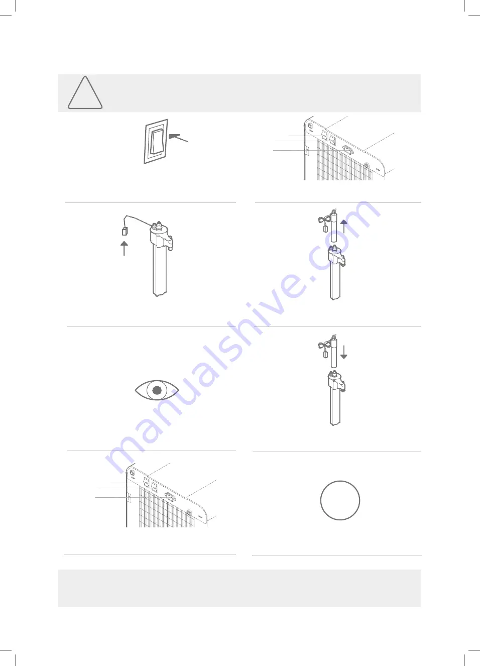
UV LAMP REPLACEMENT


Turn OFF both 

green 

and 

red 

switches 

[22] & [23].

Open the front door chapter 2.5 [9] and 
disconnect the UV lamp.


Check the interior of the Firewall

™ 

for damage

or scaling (remove and descale if necessary).


Reconnect the power cable [25] and turn ON 
both 

green 

and 

red 

switches [22] and [23].


Disconnect the power cable [25].


Pull the UV lamp carefully.


Introduce the new lamp carefully and connect 
the UV plug.


Dispense water, check for UV error and 
carefully check for UV light presence.


23 22

25


0


The UV lamp can cause harm if improperly used, please check the safety precautions before 
attempting to replace the UV lamp.


!

23 22

25


2


4


6


Summary of Contents for WL7

Page 1: ...WL7 FIREWALL Technical Manual ...

Page 2: ...ationsystemsshouldbecombinedwithselectedwatertreatment components to create a system specifically tailored for each application by trained and qualified personnel Products manufactured and marketed by Waterlogic and its affiliates are protected by patents Waterlogic International Limited andWLI TradingLimitedreserve the right in order toreflectcontinuousresearchanddevelopment toamendorchangespecif...

Page 3: ...LING INSTRUCTIONS 24 4 4 FILTER REPLACEMENT 27 4 5 UV LAMP REPLACEMENT 28 5 PROGRAMMING ANDSPECIAL FEATURES 29 5 1 PROGRAMMING INSTRUCTIONS 29 1 Hot Water Setpoint 30 2 Extra Hot Water Setpoint 30 3 Filter Change Timer 30 4 Energy Saving 31 5 UV Sensor 31 5 2 MODEL CONFIGURATION 32 5 3 SPECIAL FEATURES 32 6 SCHEMATICS 33 6 1 HYDRAULIC COMPONENTS 35 6 2 EXPLODED VIEW DIAGRAM AND PARTS LIST 36 6 3 E...

Page 4: ...the main water are supplied by the technician Do not reuse connectors Indoor use only never expose to direct sunlight heat sources to freezing temperatures ambient air temperature above 32 C 86 F and keep the unit away from excessive humidity Ensure there is proper ventilation ensure there is adequate clearance around the unit to allow refrigeration system condenser to dissipate heat Warmer enviro...

Page 5: ... faucet The replacement of the UV C must be done by Waterlogic or approved Waterlogic distributors and with power supply disconnected The UV lamp must be replaced at 6 month intervals or when necessary Do not operate if damaged if the machine is damaged unplug for safety contact Waterlogic or authorized distributor for repair service and deinstallation to avoid risks Caution hot water Waterlogic m...

Page 6: ...ation systems have been tested and certified to rigorous CE Standards END OF LIFE Waterlogic manufacturing Qingdao is certified to ISO 9001 2015 by Intertek This system has been tested and certified by Water Quality Association according to NSF ANSI 42 NSF ANSI 53 NSF ANSI 55 Class A NSF ANSI P231 USEPA Guide Standard and Protocol for Testing Microbiological Water Purifiers and NSF ANSI 372 for le...

Page 7: ...nsing options Intuitive user interface with bottles saved counter another feature of the WL7 FW is the environmentally friendly information of bottle saved counter This feature monitors dispense time to estimate how many bottles are saved during the use of the product To read more check chapter 5 Child safeguard screen automatically defaults back to cold selection to prevent accidental dispensing ...

Page 8: ... INFORMATION Ambient Rotate to select Bar with dynamic glowing chiller ON Bar static chiller OFF Ice setpoint achieved ON hot water option the white arrows indicate the current temperature of the water Left hot tank cold Right current setpoint 75 87 C or 93 C Press to dispense Hot Extra Hot COLD HOT ...

Page 9: ...5 Recommended inlet water pressure bar 2 5 3 5 Recommended CO2 pressure bar 3 Recommended inlet water temperature C 5 25 Working room temperatures C 2 37 UV Lamp change interval 6 months Electrical Compressor power W 110 Pump power W 10 Fan power W 16 Mixing motor W 25 Control power W 19 Heating element power W 500 800 model dependent UV Lamp W 13 Total max power HCAS W 993 24 hour standby power c...

Page 10: ...ain plug Ice Bath Yes Filter configuration depended on incoming water conditions TECHNICAL DATA WL7 Firewall Model ID Description F 7FX M HCAS HVL621NX XX YYY Waterlogic WL7 HCAS Mini 500W Climate Class N F 7FX M HCAS HVL621TX XX YYY Waterlogic WL7 HCAS Mini 500W Climate Class T F 7FX M HCAS HEL621NX XX YYY Waterlogic WL7 HCAS Mini 800W Climate Class N F 7FX M HCAS HEL621TX XX YYY Waterlogic WL7 H...

Page 11: ...Until level probe detects water ON S3 S4 S5 No Ice On Probes OFF S3 S4 S5 Ice On Probes S1 SetPoint E1 ON S1 SetPoint E1 OFF S2 105 C E1 OFF Requires Manual Reset PRODUCT INFORMATION These diagrams are for reference and understanding the WL7 FW some features might not be included on your machine More detailed information can be seen in Chapter 6 1 and electrical diagram on Chapter 6 3 Water config...

Page 12: ...V5 SV7 SV6 Until level probe detects water ON S3 S4 S5 No Ice On Probes OFF S3 S4 S5 Ice On Probes S1 SetPoint E1 ON S1 SetPoint E1 OFF S2 105 C E1 OFF Requires Manual Reset PRODUCT INFORMATION These diagrams are for reference only some features might not be included on your machine More detailed information can be seen in Chapter 6 1 and electrical diagram on Chapter 6 3 Water configuration cold ...

Page 13: ...play Cover 12 WL7 UI Button Graphic Lens 13 WL7 UI Knob No Description 14 WL7 Left side panel 15 Plastic Handle Black 16 Unit Rubber Feet 17 WL7 Down base 18 WL7 High Efficiency Condenser 19 WL7 Support corner left right 20 JG Bulkhead Connector Union 1 4 21 WL7 Back panel 22 Switch Heater Compressor Green 23 Switch Power Red 24 Fuse Holder Fuse 220V 10A Fuse Holder Fuse 110V 15A 25 Socket for Plu...

Page 14: ...you can refer to the examples below 1269 mm 273 mm 427 mm 839 mm 399 mm 397 mm 401 mm 519 mm 2 PRODUCT DIMENSIONS 3 PRODUCT LABEL Machine Model Year 18 Month A L Jan Dec C March Day 13 Machine Number 004 PRODUCT INFORMATION Model S N LB2H634SB18C13004CN1 F 7FX M HCAS HVL621NX XX YYY ...

Page 15: ...16 inch water pipe John Guest fittings moulded plug fitted CO2 Gas if required CO2 Regulator and customer handbook Allow 1 hour to complete installation The Waterlogic units must be installed according to the local guidelines A 350kpa pressure reducing valve and dual check valve must be connected at the water supply The Waterlogic units should not be connected to water supplies of unknown bacteria...

Page 16: ...en the front door unscrewing 9 and visually inspect the internals of the product 1 2 Connect the water supply chapter 2 5 26 Ensure the green switch on the rear of the machine chapter 2 5 22 is in the OFF position and connect the unit to a power supply and CO2 check CO2 instructions on 3 3 page 14 Turn ON the red power switch chapter 2 5 23 and follow instructions on the display screen It should t...

Page 17: ...itiser from contacting eyes clothing and any other surfaces it could damage Turn OFF the water supply and open the front panel 9 to access the filter Ensure CO2 supply is on and dispense 500 ml of sparkling water from the faucet This will let the pump refill the tank with water that contains sanitiser solution Turn ON the water supply Dispense cold water until water with sanitiser solution comes o...

Page 18: ... and use test strips to make sure there is no sanitiser left Flush 5 litres of ambient and sparkling until there is no sanitiser in the system After the sanitiser has been completely flushed the green compressor and heater switch can now be turned ON 9 10 11 INSTALLATION INFORMATION ...

Page 19: ...ensuring that the O ring seal is correctly located 5 After the installation of the machine connect the pipework from the regulator b to the machine d and secure the gas bottle in position with a strap or chain so it will not fall over 6 Open the tap on the gas bottle and set the pressure to 3 bar c 7 Dispense 500 ml of sparkling water and allow a full regeneration 8 Re check and readjust the CO2 p...

Page 20: ...cal connections Remove selector button and UI PCB housing cover to expose UI PCB Remove 2 screws to remove UI PCB from housing Install new Contactless UI PCB to housing cover Additional steps required if both PCBs required for change as per note above Full steps not shown in visual process A Remove all electrical connections from main PCB Take note of connections B Apply pressure to the 4 retainin...

Page 21: ...cover Reverse steps to fit new UI PCB Knock through the protective cover shown Fit grommet provided to opening in machine to protect the harness Feed harness through opening shown in image and across to the opening on the rear of the machine 3 4 5 6 7 8 9 Test machine operation Pedal IR harness is labelled as shown Connect accordingly ...

Page 22: ...e of the key factors is keeping the machine clean to avoid contamination and staining 4 1 MAINTENANCE REPLACEMENT COMPONENTS Component Recommended replacementfrequency UV lamp Chapter 6 1 14 Every 6 months or as required Filters Chapter 6 1 12 Every 6 months or as required Hot tank Chapter 6 1 31 Replace every 5 6 years depending on usage Ice detection probes Chapter 2 4 S3 S4 S5 Verificationevery...

Page 23: ...fy if the machineiscoolingandheatingproperly Measurestaticandnominal working pressures for proper operation Check the maintenance screen for the temperatureset pointsanderrors Ifneededcheckchapter5andchapter7 Check ifthe water supply isopen if it is closed there might be a leak in the system Verify every function presentinthe machine for correctfunctionality Press five times the ambient dispense i...

Page 24: ...er housing with descaler 50g 3 and mix with a glass of hot water 4 Open the front panel 9 to access the filter Replacethe filter withthe housing with descaler bypass the other filters if applicable 9 STAINLESS STEEL TANK DESCALING The hot tank is made from stainless steel Ensure descaling solution is compatible with stainless and always flush the unit completely Dispose all chemicals in an environ...

Page 25: ...toimprove the descale efficiency Turnthe greencompressorandheater switch 22 OFF Turn OFF the water supply 13 Pinchthedispensingtubeorblockthehot dispenseanddispense hotwater until water comesout the faucet by the vent hole Wait15minutes frontdoormustbeclosed due to a safety switch Dispense atleast 2litres of hot water to cool thetank Drainthehottankthroughthedrainplugin the front and replace the d...

Page 26: ...sh until water runs clear Turn the green compressor and heater switch 22 ONandallowthehottankto heat up Dispense to a glass and check the temperature 1 If you used the pincher don t forget to remove it from the machine after the descaling procedure is finished In every service maintenance the machine must be sanitised Please follow the instructions in chapter 3 2 i ...

Page 27: ... 6 months and FLUSHED before being connected to the machine 1 Turn Off water supply Ensure the new filtersare flushed before step 4 and5 5 Replace the filters Dispense a cup and taste the water Ifneededflush5litrestoensureagood quality water 2 Dispense to relieve the water pressure 4 Open the front panel 9 toaccess the filter 6 TurnONthewatersupplyandcheckforleaks The filters are now replaced 8 9 ...

Page 28: ...connect the UV lamp ChecktheinterioroftheFirewall fordamage or scaling removeand descaleif necessary Reconnectthe power cable 25 and turn ON bothgreenandredswitches 22 and 23 Disconnect the power cable 25 Pull the UV lamp carefully Introducethenewlampcarefullyandconnect the UVplug Dispense water check for UV error and carefullycheckforUVlightpresence 23 22 25 0 The UV lamp can cause harm if improp...

Page 29: ...factory setting ON Hot water setpoint factory setting 87 C Extra hot water setpoint factory setting 95 C But also allows you to see do Errors the machine is experiencing Type of UV sensorpresent Reset the filtertimer Reset bottles savercounter To change the factory settings follow the instructions below ON ON ON 1 2 1 2 1 2 ON ON 1 2 1 2 Removethepanel 14 bytakingscrewsin the backandfront withthef...

Page 30: ...0 C 3 Filter change timer The filter change timer comes OFF by default Tochange this value change the DIP switchesasshownbelowtogetthreemonths sixmonthsortwelvemonths DP4 OFF DEFAULT 3 MONTHS 6MONTHS 12 MONTHS To reset the filter timer after a filter replacement enter maintenance screen press and hold the dispense button for approximately 5 seconds until you hear a single beep The filter iconwill ...

Page 31: ...vings are significant when the unitis idle so the energy saving option should be leftON DP5 ON OFF DEFAULT 5 UV sensor The sensor of the Firewall system can be used in UVC or CDS mode The UV sensor mode must remain in the factory setting and must not be altered except when this sensor is changed from one type to another DP6 UVC CDS DEFAULT ON 1 2 ON 1 2 ON 1 2 ON 1 2 Every one of the selections ma...

Page 32: ... toavoidtrippingthe overheatprotection Checkchapter 7 4for the related error andtroubleshooting 2 Ice Bath circulatormotor The Ice Bath has got a mixing motor check chapter 6 1 that ensures movement of the water Thisallows for a uniform temperature all around the bath which also prevents the accumulation of ice in colder areas Thecirculationmotorcomesonwhendispensingandremainsonfor4minutesafter di...

Page 33: ...33 ENG2036 16 01 19 6 SCHEMATICS ...

Page 34: ... the flow diagram in chapter 2 4 62 60 61 59 63 58 64 65 72 57 73 56 74 76 81 75 79 83 80 78 77 82 66 67 68 55 47 48 54 52 50 51 19 69 20 46 9 7 53 71 40 41 43 70 42 34 13 18 6 11 4 10 16 14 17 32 44 39 1 25 2 5 24 31 33 3 15 23 21 38 30 45 8 22 28 27 29 35 12 26 37 36 ...

Page 35: ...1 4 Reducing Fitting 59 1 4 PE Pipe 20 Ice Bath Assembly 60 JG Equal Elbow Connector 1 4 21 1 4 PE Pipe 61 75 GDP RO DC Pump 22 Drain Valve 62 JG Equal Elbow Connector 1 4 23 1 4 PE Pipe 63 1 4 PE Pipe 24 JG Equal Tee Connector 1 4 64 JG Non Return Valve 1 4 25 1 4 PE Pipe 65 1 4 PE Pipe 26 JG Equal Tee Connector 1 4 66 JG Equal Elbow Connector 1 4 27 MS DC Solenoid Valve SWV24 01 67 Ice bath Spar...

Page 36: ...W DIAGRAM AND PARTS LIST B 15 D C 14 70 69 2 A 68 1 11 13 9 7 12 8 10 3 4 5 6 A 20 19 21 22 18 17 16 B 72 71 65 64 66 73 53 52 56 49 50 74 63 47 8 4 55 60 61 67 58 59 62 46 54 45 C 31 32 39 38 42 34 33 44 35 37 36 40 41 43 26 27 28 30 29 23 25 24 D ...

Page 37: ...I PCB with Knob LED 27 WL7 UI Sealing Cover WL 7 Spring metal cover for PCB Cover 29 WL7 UI Button 30 WL7 Knob Light Diffuser 31 WL7 Drip Tray 32 WL7 Drip Tray Grill 33 WL7 Door Dispense Area Insert 34 WL7 Back Splash Trim 35 WL7 UI Insert Trim 36 WL7 UI Display Cover 37 WL7 Door Parent Part 38 WL7 Waterfall Light Diffuser 39 WL7 LED PCB for waterfall back light 1 5L 120V 500W Universal Hot Tank S...

Page 38: ...n M Ice Bath Mixing Motor HS Hot Tank Temperature Sensor T Transformer PCB P T Photo Transistor S1 S Valve Cold Water Out S2 S Valve Sparkling Water Out S3 S Valve Sparkling Water In S4 S Valve Ambient Water Out S5 S Valve Hot Water In S6 S Valve Fill Ice Bath S7 S Valve Inlet Solenoid P Pump IP Ice Probe IBLS Ice Bath Water Level Sensor Drawing 2016 12 09 No SLS Sparkling Tank Level Sensor HIGH V...

Page 39: ...nsity of Ultraviolet Detection S1 S Valve Cold Water Out S2 S Valve Sparkling Water Out S3 S Valve Sparkling Water In S4 S Valve Ambient Water Out S5 S Valve Hot Water In S6 S Valve Fill Ice Bath S7 S Valve Inlet Solenoid P Pump IP Ice Probe IBLS Ice Bath Water Level Sensor Drawing 2016 12 15 No SLS Sparkling Tank Level Sensor 39 SCHEMATICS ENG2036 16 01 19 HIGH VOLTAGE ELECTRICAL HAZARD WL7Firewa...

Page 40: ...nd open the door 9 Hot tank located inside the machine Locate th Unplug the power cord from the rear of unit 25 Removetheleftpanel 14 by takingscrewsin the backandfrontwiththe frontdooropen Press the reset button click Check continuity with multimeter Connectthepower 25 TurnONredbutton 23 and fill the hot tank TurnONgreenbutton 22 Wait 10 minutes for the hot tank to heat up Verify the proper opera...

Page 41: ...ing a problem with the thermistor Heater will be shut off and hot and extra hoticonswill be ghosted in the dispense screen COMMON TROUBLESHOOTING 1 Ensure thermistor is connected properly and fully installed in the hot tank 2 Replace thermistor sensor RESET the ERROR by turning OFF and ON after 5 seconds the red power switch 7 4 HOT TANK HEATING ERROR Rate of rise error has been detected This avoi...

Page 42: ... 6 SPARKLING WATER LEVEL ERROR Sparkling water level or pump time out error The sparkling water injection pump cycled twice without filling carbonator COMMON TROUBLESHOOTING 1 Limited water supply Verify that water supply is open and dispense ambient water to validate water flow 2 CO2 pressure too high Ensure 3 bar 42 5 PSI maximum 3 Sparkling water level probe Verify all connections from probe to...

Page 43: ...hin an hour this error will also show COMMON TROUBLESHOOTING 1 Check for leaks 2 Ensure adequate watersupply 3 Check to make sure Ice Bath level sensor is properly connected 4 Check Ice Bath fill solenoid valve SV6 5 Replace Ice Bath level sensor RESET the ERROR by turning OFF and ON after 5 seconds 7 9 DISPENSE TIME OUT Indicates a 2 minute continuous dispense has been detected in operating mode ...

Page 44: ... power cord to verify not lit Green switchnotlit Display not lit Failed power socket with electromagnetic interference Replace power socket with electromagnetic interference filter EMI filter EMI Defective red power switch Replace red power switch 23 Red Bad transformer Replace transformer switch lit Green switch lit Black power connector to the PCB is not properly connected Properly connect Bad f...

Page 45: ...efore dispensing more cold water assure that the condenser coil chapter 2 5 18 is clean and with enough space for correct ventilation minimum of 100 mm Check If the red and green Switches are ON chapter 2 5 Compressor is not running No power to refrigeration elements 22 23 Check power socket chapter 2 5 25 and cable Check fuse chapter 2 5 24 Repair or replace compressor Check for leaks in the refr...

Page 46: ...Sleep Mode by using the dispensing knob and allow 10 minutes for the water to heat up You can check the heating progress on the screen check chapter 2 2 User Interface No power to the Heater Green Button 22 is Switched OFF Turn Green Button Switch chapter 2 5 22 ON Overheat thermostat is activated Ensure the Hot Tank is Filled and click to deactivate the overheat thermostat Chapter 7 1 Loose conne...

Page 47: ...caled over Inspect and Descale Tank as nee ded Expansion chamber is not sealed properly Replace the Hot Tank No flow or restricted flow of water Closed or Partially Closed water supply valve to the unit Open water supply valve Hot Tank outlet hole is scaled over Inspect and Descale Tank as nee ded Tubing is creased or has a kink in it Inspect and replace tubing as necessary No flow or restricted f...

Reviews: