


38
39
WL3000 Technical Manual - May 2014
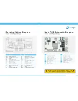
Electrical Wiring Diagram
Cold and Hot
Main PCB Schematic Diagram
Cold and Hot
DANGER HIGH VOLTAGES PRESENT ON THIS PCB
CARE MUST BE TAKEN WHEN LIVE TESTING
Mark
Description
Mark
Description
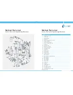
20S1
Hot solenoid valve
PS1
Control power switch
20S2
Cold solenoid valve
PS2
Comp & heater power switch
26H
Thermostat for overheat-hot tank Q 4 - 5
Transistor
BT
Ballast
RL 1-5
Relay
CDS
CDS for UNV Lamp
S 1 - 4
Temperature setting switch
CPU
Central processing unit + PCB
S
Glow starter
DS
Drip tray sensor
T
Transformer for PCB
EF1
Enclosed fuse (1A)
TF
Internal thermal fuse
H
Hot water heater
TH1
Thermistor-hot water
MC
Motor for compressor
TH2
Thermistor-cold water
MFC
Motor for compressor IN
UV
UV lamp
PF
Power Fuse (250V/10A)
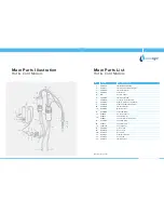
A
230V from Red Switch
B
230V to UV Ballast
C
Output to UV Lamp
D
230V to Heater
E
230V from Green Switch
F
230V to Compressor
H
Cold Thermostat
I
Hot Thermostat
J
Not used
K
UV Sensor
L
Drip Tray Sensor
N
12 Pin Ribbon Cable
O
9 Pin Ribbon Cable
R
24V DC to Cold Valve
S
24V DC to Hot Valve
V
24V DC IN from Transformer
W
230V DC to Transformer
X
Earth
Y
PCB Configuration