background image

Page 8


           EE Man u al

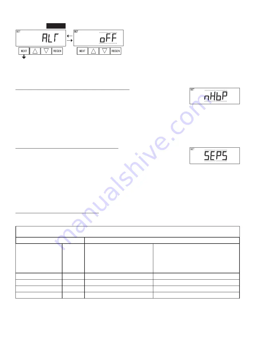
Step 5CS –

 This display will not appear if 

1.0T

 was selected in Step 

2CS. Allows selection of one of the following using 


or 

:

• the Control Valve to have no hard water bypass;
• the Control Valve to act as an alternator;
• the Control Valve to have a separate source during the regeneration 
cycle; or
• the Control Valve to operate with the System Controller.

Select OFF when none of these features are used.

Only use Clack No Hard Water Bypass Valves or Clack Motorized Alternating Valves (MAV) with these selections. Clack No Hard Water 
Bypass Valves (1” or 1.25” V3070FF or V3070FM) are not designed to be used with the alternator or separate source functions.

Step 5CS

Selecting the Control Valve to act as an alternator:

519.0 and higher = Use 3-wire Interconnect Cables for all communication between units.
518.3 and lower = Use 2-wire Interconnect Cables for twin alternators with independent 

fl

 ow meters.

Con

fi

 guring the Control Valve for No Hard Water Bypass Operation:

Select nHbP for control operation. For no hard water bypass operation the three wire communication cable 
is not used. 

Selection requires that a connection to MAV or a Clack No Hard Water Bypass Valve is made to the two 
pin connector labeled MAV located on the printed circuit board. If using a MAV, the A port of the MAV 
must be plugged and the valve outlet connected to the B port. When set to nHbP the MAV will be driven 
closed before the 

fi

 rst regeneration cycle that is not FILL or SOFTENING or FILTERING, and be driven 

open after the last regeneration cycle that is not FILL.

NOTE: If the control valve enters into an error state during regeneration mode, the no hard water bypass 
valve will return to the open Position, if not already there.

Con

fi

 guring the Control Valve for Separate Source Operation:

Select SEPS for control operation. For separate source operation the three wire communication cable is not 
used. 

Selection requires that a connection to a Clack Motorized Alternator Valve (MAV) is made to the two pin 
connector labeled MAV located on the printed circuit board. The C port of the MAV must be connected to 
the valve inlet and the A port connected to the separate source used during regeneration. The B port must 
be connected to the feed water supply.

When set to SEPS the MAV will be driven closed before the 

fi

 rst regeneration cycle, and be driven open 

after the last regeneration cycle.

NOTE: If the control valve enters into an error state during regeneration mode, the MAV will return to the 
open position, if not already there.

NOTE: If the control valve is in an error state during regeneration mode the MAV will close the B port and keep open the A port until the error is 
corrected and reset.

Prior to starting the programming steps, connect the communication cable to each control valve board’s three pin connector labeled ‘COMM 

CABLE’. Also connect the meter cord to either control valve to the three pin connector labeled ‘METER’.

Softener Valve Programming Steps

Con

fi

 guration Settings

Step 5CS

Set to ALT A

Connect  the outlet plumbing of ALT A 

valve to the MAV’s A port and connect 

the MAV’s two pin wire connector to the 

two pin connector labeled “DRIVE” on 

the ALT A valve

Set to ALT b

Connect the outlet plumbing of ALT b valve to the 

MAV’s B port. No electrical connections are required 

between the ALT b valve and the MAV.

Softener System Setup

Step 10S

Set System Capacity

Set System Capacity

Softener System Setup

Step 11S

Set to ‘AUTO’

Set to ‘AUTO’

Softener System Setup

Step 12S

Set regeneration time option to ‘on 0’.

Set regeneration time option to ‘on 0’.

Installer Display Settings

Step 3I

Set Day Override to “oFF”

Set Day Override to “oFF”

If set up for a 

fi

 lter, in Step 5F set Volume Capacity in Gallons; in Step 6F select Regeneration Time Option “on 0”; and in Step 3I select Day 

Override “oFF”.

Summary of Contents for EE

Page 1: ...Water Specialist EE Control Valve Programming and Cover Drawing Manual...

Page 2: ...Page 2 EE Manual...

Page 3: ...rations and Functions 5 User Displays 6 Configuration Settings 7 OEM Softener System Setup 11 Setting Options Table 14 OEM Filter System Setup 15 Installer Display Settings Regeneration Type Auto 17 I...

Page 4: ...nternational Supply Voltage 120 V AC 230V AC Supply Frequency 60 Hz 50 Hz Output Voltage 15VDC 15VDC Output Current 500 mA 500 mA Refer to Control Valve Service Manual for other drawings and part numb...

Page 5: ...e regeneration Pressing and holding for 3 seconds will initiate an immediate regeneration Pressing while in regeneration will advance to the next cycle Pressing in the program levels will go backwards...

Page 6: ...f Day Push NEXT until time of day screen is displayed Press and hold until SET TIME is displayed and the hour flashes once Press or until the correct hour is displayed Then press NEXT The minutes will...

Page 7: ...witch cannot be used for both controls on0 If the dP switch is closed for an accumulative time of 2 minutes a regeneration will be signaled to the unit In a twin alternating system the MAV will transi...

Page 8: ...ntrol operation For separate source operation the three wire communication cable is not used Selection requires that a connection to a Clack Motorized Alternator Valve MAV is made to the two pin conne...

Page 9: ...ice Position MAV piston rod Extended WS1 WS1 25 and WS1 5 Valves For Clack Corporation alternator systems using WS1 WS1 25 and WS1 5 valves there will be an option to delay the last two cycles of rege...

Page 10: ...to System Controller For communication between control valve and System Controller a three wire communication cable is required Selection requires that a connection to a Clack No Hard Water Bypass V30...

Page 11: ...on time set This screen is not viewed when Step 2S is set to Filtering Press NEXT to go to Step 5S Press REGEN to return to previous step Step 4S Step 5S Select the time for the first cycle using or F...

Page 12: ...not available on 0 is the default if Step 2CS is set to 1 0T and NORMAL on 0 is not available See Setting Options Table for more detail Press NEXT to go to Step 14S Press REGEN to return to previous...

Page 13: ...e meter Ranges from 1 to 200 gallons Press NEXT to go to Step 16S Press REGEN to return to previous step Step 16S Set Relay Deactivate Time using or If Set Time on is selected in Step 14S the relay wi...

Page 14: ...e capacity reaches 0 Time of regeneration will not be allowed to be set because regeneration will always occur when volume capacity reaches 0 Any number On 0 oFF Reserve capacity NOT automatically est...

Page 15: ...the first cycle using or Press NEXT to go to Step 4F Press REGEN to return to previous step Step 3F Step 4F Select the time for the second cycle using or If Step 2F is set to FILTERING REGEN press NE...

Page 16: ...ng on Relay activates after a set number of gallons have been used while in service and then deactivates after the meter stops registering flow and the set time period has expired Gallons Filtering Re...

Page 17: ...e from 1 to 28 regeneration initiation will be called for on that day regardless of actual water usage Set Day Override using or number of days between regeneration 1 to 28 or oFF See Setting Options...

Page 18: ...tween regeneration 1 to 28 See Setting Options Table for more detail on setup Press NEXT to go to step 3I Press REGEN to return to previous step Step 2I Step 3I Next Regeneration Time hour Set the hou...

Page 19: ...Step 2I Step 3I Scroll through days 1 to 7 using NEXT Use or to turn regen ON or OFF for each individual day After completing the 7th day press NEXT to go to Step 4I Press REGEN to go to previous dis...

Page 20: ...ows the total number of regenerations that have occurred since startup Press the NEXT button to go to Step 6D Press REGEN to return to previous step Step 5D Step 6D Error Log This display shows a hist...

Page 21: ...f A then the tank with the valve on it was in service if b the tank with the in out head on it was in service The next three digits represent the number of hours ago that the transfer occurred The dis...

Page 22: ...Page 22 EE Manual...

Page 23: ...EE Manual Page 23...

Page 24: ...MAL not adjustable Any number Reserve capacity not automatically estimated 28 day Regeneration occurs at the next Regen Set Time when the specified number of days between regenerations is reached 7 da...

Reviews: