I. Methods for Compressor Maintenance
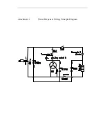
1. The single hermetic compressor has three terminals on the body:
R
•
primary coil or moving coil
t
.
.
S
•
starting coil
C
•
public poin
2. Judgment of compressor exhaust pipe oil vent
Generally, little oil discharges from a hermetic compressor. If oil is found to drip from the exhaust
pipe continuously, it is shown that the compressor is discharging too much oil. Over oil discharge
is mainly because that the clearance between cylinder and piston exceeds more than 1.5 times the
stipulated maximum fit clearance. In this case, disassemble the compressor, and inspect the fit
clearance between cylinder and piston. If it is out-of-tolerance, utilize a new piston.
II. Judgment of Compressor Electrical Machine Burning
1.
Winding turnoff
detect the three- winding by using an ohmmeter or a multimeter. If the
resistance between any two windings is infinite, turnoff happens.
2.
Winding earthing
with a multimeter (at low resistance level), measure between the three
terminals from the hermetic compressor and the copper pipes out of the body respectively. If the
resistance between any one of the terminals and the ground is zero, the winding is short-circuited
3.
Winding short
with an ohmmeter or a multimeter, measure the insulation resistance between
any two windings. If the insulation resistance is too low, the windings are short-circuited
III. Compressor Shaft Seizing and Cylinder Blocking
Compressor shaft seizing and cylinder blocking mean that broken-in surfaces of moving parts hug
each other and can no longer run, which are caused by bad lubricating parts, oil cut-off or blocked oil
circuits.
Troubleshooting: disassemble the compressor to determine where the failure takes place. In the
case of shaft seizing, knock on the seized surface or counterbalance with a wood stick or a copper rod.


