background image


Attachment 3


Compressor Working Principle and Failure Analysis 


Brief outline of compressor cooling working principle   

The water dispenser compressor cooling system mainly includes compressor, condenser, filter, 

evaporator, capillary and other components. 


The water dispenser adopts a rotary compressor filled with cool-producing medium R134a. 

R134a gas is, by the compressor, compressed into high-pressure gas, goes into the condenser and then 

becomes high-pressure liquid. After being filtered by the drying filter, the liquid has its pressure 

reduced through the capillary, and then enters the evaporator. Because the evaporator has much larger 

volume than that of the capillary, liquid freon will absorb a great deal of heat from outside to become 

gas, and finally returns to the compressor, forming the closed circulatory system. 


Compressor common failures and their maintenance methods 

Because the compressor and electrical machine are both sealed, there are a suction pipe and a exhaust 

pipe but no cut-off valve on the body, and capillary throttle is utilized, the compressor may also fail to 

work or cause the electrical machine to be burned when the electrical machine’s cooling conditions 

become worse or failures happen in the system. Below are some methods for judgment and 

maintenance of common compressor failures. 


Drying filter 

Capillary 

Evaporator 

Condenser 

Compressor 

Summary of Contents for DLC-100R

Page 1: ...DLC 100R WATER DISPENSER SERVICE MANUAL Prepared By Water Dispenser Development Dept NOV 2004 S N DLC100R001...

Page 2: ...n Components and Their Functions 1 4 List of Universal and Wear Parts 2 5 Common Failures and Maintenance Methods 2 6 Cautions 3 7 Attachment 1 Wiring Principle Diagram 4 8 Attachment2 Exploded View 5...

Page 3: ...l tank by using R134a as the cooling medium Under the auto control of the temperature controller keep the temperature of water and refrigerator below 10 for instant use II Main Technical Parameters Po...

Page 4: ...eplaceable and easy cleaning IV List of Universal and Wear Parts See the exploded view in Attachment 2 Power switch 5 115V 10A plastic tumbler switch Hot tank assembly 35 115V 60Hz 420W insulation cot...

Page 5: ...ld tank becomes loose 2 The inside pipeline becomes loose or damaged 1 Open the upper cover and fix the sealing ring 2 Inspect or replace the inside silica gel tube VI Cautions 1 Wait for 5 10 minute...

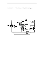
Page 6: ...Attachment 1 Water Dispenser Wiring Principle Diagram...

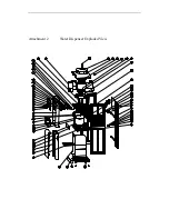
Page 7: ...Attachment 2 Water Dispenser Exploded View...

Page 8: ...e evaporator Because the evaporator has much larger volume than that of the capillary liquid freon will absorb a great deal of heat from outside to become gas and finally returns to the compressor for...

Page 9: ...r a multimeter If the resistance between any two windings is infinite turnoff happens 2 Winding earthing with a multimeter at low resistance level measure between the three terminals from the hermetic...

Page 10: ...If it moves slightly that would be good and otherwise replace the compressor...

Reviews: