background image

6

ELECTRICAL

Disconnect power before working on  

pump, motor, pressure switch or wiring

Motor may be hot. Allow to cool 20 

minutes.
Water pressure may have built up in 

the pump, pipes and/or tank. Drain 

water to relieve pressure.

!
!

4.  Use wire size specified in Wiring Chart (below). If    

  possible, connect pump to a separate branch circuit   

  with no other appliances on it.

5.  Do not ground to a gas supply line.

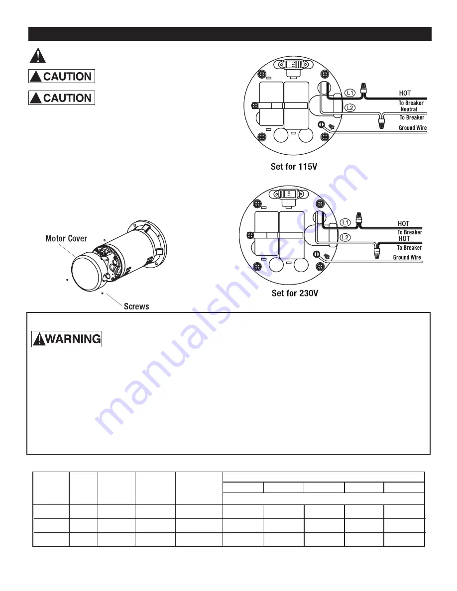
6.  Wire motor according to diagram on motor nameplate.  

  If nameplate diagram differs from diagrams above,    

  follow nameplate diagram.

7.   If this procedure or the wiring diagrams are    


  confusing, consult a licensed electrician. 

NOTICE


Pump must be on dedicated circuit  


  not shared by any other equipment

.

Wiring Connections


                 Risk of electric shock. Electricity 

can shock, burn or kill.
1.  To avoid dangerous or fatal electrical shock, turn OFF  

  power to motor before working on electrical   


 connections.

2.  Ground motor before connecting to electrical power   

  supply. Failure to ground motor can cause severe or   

  fatal electrical shock hazard.

3.  Supply voltage must be /- 10% of nameplate  

  voltage. Incorrect voltage can cause fire or damage   

  motor and voids warranty. If in doubt consult a  


  licensed electrician.

Motor Voltage Settings

Motors are designed to run on either 115 volt or 230 volt 

current. Be sure the motor’s current is set to match the 

current being supplied to your motor from the electrical 

source. 

To set your motor to the correct voltage, first remove the 

rear cover plate. Next slide the voltage conversion switch 

to the correct voltage. WIRING THE PUMP FOR THE 

INCORRECT VOLTAGE WILL DAMAGE THE PUMP.


Wiring Chart Recommended Wire and Fuse Sizes for 115 and 230 volts


BRANCH


AWG  


 DISTANCE IN FEET FROM MOTOR TO SUPPLY 


 FULL LOAD   

FUSE/BREAKER

    MIN. WIRE 

0-100   

101-200   

201-300   

301-400   

401-500 

  MOTOR HP   VOLTS   

AMPS    RATING AMP    SIZE (mm

2


  AWG WIRE SIZE (mm

2


115/230 

18.5/9.25 

30/15 

10/14 (5.5/2) 

10/14 (5.5/2) 

8/14 (2/2) 

6/14 (14/2) 

6/12 (14/3)  4/10 (21/5.5) 


1-1/2 

115/230 

22/11 

30/15 

10/14 (5.5/2) 

10/14 (5.5/2)  8/14 (8.4/2) 

6/12 (14/3)  4/10 (21/5.5)  4/10 (21/5.5) 


115/230 

27.0/13.5 

35/20 

8/12 (8.9/3) 

8/12 (8.9/3) 

8/12 (8.4/3)   6/10 (14/5.5)  4/10 (21/5.5)  4/10 (21/5.5) 

Summary of Contents for WA10PLS

Page 1: ...Owner s Manual WAPLS Series Thermoplastic Sprinkler Pumps General Safety 2 Installation 3 5 Electrical 6 Operation 7 Troubleshooting 8 Repair Parts 9 Warranty 10 WA10 15PLS WA20PLS TABLE OF CONTENTS ...

Page 2: ...aring insulted protective shoes under flood conditions Contact your local electric company or a qualified licensed electrician for dicconnecting electrical service prior to pump removal Follow all local electrical and safety codes as well as the National Electrical Code NEC and the Occupational Safety and Health Act OSHA Replace damaged or worn wiring cord immediately Do not kink power cable and n...

Page 3: ...ly operates at high temperature and will be too hot to touch It is protected from heat dam age during operation by an automatic internal cutoff switch Before handling pump or motor stop motor and allow it to cool for 20 minutes Well Pipe Installation NOTICE It is recommended that pump be in stalled in well ventilated enclosure Use installation method below which matches your water source 3 INSTALL...

Page 4: ...A and 3B A Vertical from Surface Water to Pump 1 Foot Valve with Strainer attached to PVC pipe 2 Install check valve in horizontal pipe B Horizontal from Surface Water to Pump 1 Attach Foot Valve to PVC pipe 2 Next attach the Strainer Basket to Foot Valve 3 Install check valve in horizontal pipe Figure 2 Driven point installation multiple well points To sprinkler heads Discharge pipe Gate valve Ga...

Page 5: ...ell 1 Bolt pump to solid level foundation 2 Support all piping connected to pump 3 Wrap 1 1 2 to 2 layers of Teflon tape clockwise as you face end of pipe on all male threads being attached to pump 4 Tighten joints hand tight plus 1 1 2 turns Do not overtighten 5 Replace prime plug with pressure gauge This will aid in sizing zones troubleshooting and following pump performance chart NOTICE For lon...

Page 6: ...motor can cause severe or fatal electrical shock hazard 3 Supply voltage must be within 10 of nameplate voltage Incorrect voltage can cause fire or damage motor and voids warranty If in doubt consult a licensed electrician Motor Voltage Settings Motors are designed to run on either 115 volt or 230 volt current Be sure the motor s current is set to match the current being supplied to your motor fro...

Page 7: ...ength of horizontal run 10 3 m of horizontal suction pipe 1 30 5 m of vertical lift due to friction losses in pipe If no water is produced within 10 minutes stop pump release all pressure remove priming plug refill and try again Risk of explosion and scalding NEVER run pump against closed discharge To do so can boil water inside pump causing hazardous pressure in unit risk of explosion and possibl...

Page 8: ...WA10PLS WA15PLS WA20PLS ...

Page 9: ... PARTS EFLS10P 15P 1 HP and 1 1 2 HP Part Quantity Part Number Description 1 1 EFLS10001 O RING 2 1 EFLS10002 O RING EFLS20P 2 HP Part Quantity Part Number Description 1 1 EFLS20001 O RING 2 1 EFLS20002 O RING ...

Page 10: ...pos sible No requests for service will be accepted if received more than 30 days after the warranty expires Warranty is not transferable and does not apply to products used in commercial rental applications General Terms and Conditions Limitations of Remedies You must pay all labor and shipping charges necessary to replace product covered by this warranty This warranty does not apply to the follow...

Reviews: