background image

Hardware Guide

#

Running H/F 2

Chapter 1

Hardware Specifications ........................................................................................................... 1

Fireware OS .............................................................................................................................................................. 1
Package Contents .................................................................................................................................................. 2
About Your Hardware........................................................................................................................................... 2
Environmental Requirements............................................................................................................................ 3
Hardware Description........................................................................................................................................... 4
Restore Factory-Default Settings...................................................................................................................  10
Safety Notices .......................................................................................................................................................  11
Hinweise Zur Sicherheit....................................................................................................................................  12
Avis de sécurité ....................................................................................................................................................  13
Aviso De Seguridad ............................................................................................................................................  14

Chapter 2

Hardware Installation  ............................................................................................................. 15

Rack Mount Installation ....................................................................................................................................  16
Interface Module Installation..........................................................................................................................  21
Power Supply Installation ................................................................................................................................  22

Chapter 3

Legal and Regulatory Information  ........................................................................................ 23

Limited Hardware Warranty ............................................................................................................................  23
Declaration of Conformity ...............................................................................................................................  25
CE Notice ................................................................................................................................................................  26
FCC Certification..................................................................................................................................................  26
Industry Canada...................................................................................................................................................  26
Japan VCCI Notice (Class A ITE) ......................................................................................................................  27
Taiwan Class A Notice........................................................................................................................................  27
Mexico Notice.......................................................................................................................................................  27
Korea Notice..........................................................................................................................................................  27
RoHS Statement...................................................................................................................................................  28
WEEE Statement ..................................................................................................................................................  28
REACH Certificate of Compliance..................................................................................................................  28
Licensing ................................................................................................................................................................  29

Summary of Contents for Firebox M4600

Page 1: ...WatchGuard Firebox M4600 Hardware Guide CL4AE24...

Page 2: ...pe with them at www secplicity org Copyright and Patent Information Copyright 1998 2016 WatchGuard Technologies Inc All rights reserved WatchGuard the WatchGuard logo LiveSecurity and any other mark l...

Page 3: ...so De Seguridad 14 Chapter 2 Hardware Installation 15 Rack Mount Installation 16 Interface Module Installation 21 Power Supply Installation 22 Chapter 3 Legal and Regulatory Information 23 Limited Har...

Page 4: ...WatchGuard Firebox M4600 Running H F 2...

Page 5: ...r multiple layers of defense This guide introduces the Firebox M4600 an RoHS compliant lead free hardware product offered by WatchGuard Fireware OS The Firebox M4600 uses WatchGuard s next generation...

Page 6: ...specification describes the interfaces that are on the Firebox M4600 as shipped The Firebox also has two slots where you can install additionalinterface modules The supported interface modules are des...

Page 7: ...in a secure area such as a locked room to prevent unauthorized access Connect it to a conditioned power supply to prevent damage from sudden power changes Other M4600 environmental requirements Operat...

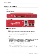
Page 8: ...rd disk this indicator is yellow Power Button The Power button on the left side of the Firebox is lit to indicate power status It is green when the Firebox is powered on and red when power is availabl...

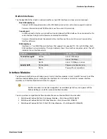
Page 9: ...terface connection status The left indicator shows interface activity Interface Modules To add more interfaces to your Firebox you can install interface modules in slots A and B You must install the i...

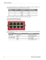
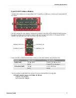
Page 10: ...e numbered from 0 to 7 Each RJ45 interface has two indicators The right indicator shows the interface link status The left indicator shows interface activity Installed in Firebox slot Number of ports...

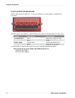
Page 11: ...icators that point down show the status of the lower interface For each interface the left indicator shows activity and the right indicator shows the link status You can purchase compatible SFP transc...

Page 12: ...r shows link status the right indicator shows activity You can purchase compatible SFP transceivers from an authorized WatchGuard reseller SFP multi mode transceiver 10GBase SR 1000Base SX 850 nm FINI...

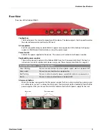
Page 13: ...with a power indicator at the top For instructions to install a replacement power supply see Power Supply Installation on page 22 Alarm reset button When the Firebox is powered on if either power sup...

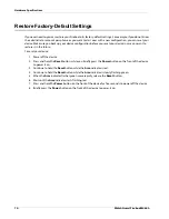
Page 14: ...future To reset your device 1 Power off the device 2 Press and hold the Reset button while you briefly press the Power button on the front of the device to power it on 3 Continue to hold the Reset bu...

Page 15: ...or openings on this equipment If you make contact with a voltage point or short out a part it can result in fire or electrical shock If the equipment is supplied with a three conductor AC power cable...

Page 16: ...nem Zeitpunkt verschlossen verstopft oder anderweitig blockiert sind Die Ventilation verhindert ein berhitzen des Ger tes Stecken Sie niemals Gegenst nde irgendwelcher Art in Schlitze oder ffnungen de...

Page 17: ...chauffe de l appareil N ins rez jamais d objet de quelque sorte dans les fentes d ouverture de cet quipement Si vous faites contact avec un point sous tension ou court circuitez un composant cela peut...

Page 18: ...el cable de alimentaci n No obstruya las aberturas de ventilaci n Estas aberturas evitan el sobrecalentamiento de la m quina Nunca introduzca objetos de ning n tipo en las ranuras o aberturas del equ...

Page 19: ...mount kit It also supports user installable components Use the instructions in this chapter to safely install your Firebox and any optional components This chapter includes instructions for Rack moun...

Page 20: ...s 2 sliding rails which can be separated into inner and outer rails o The inner rail has an extension safety lock tab o The outer rail includes a slide to extend its length It also has an extension sa...

Page 21: ...used by uneven mechanical loading Circuit Overloading Make sure you connect the device to the power supply circuit in such a way that there is no overloading of the circuits and no impact on overcurre...

Page 22: ...nner rail to the Firebox with three of the shorter flat head screws 6 Repeat these steps to attach the other inner rail and front ear bracket to the other side Attach the L shaped brackets to the oute...

Page 23: ...ls to the rack Use this procedure to mount the outer rails to the rack 1 Locate the countersink screws and conical washers C 2 Use two screws and conical washers to connect the front bracket on the ou...

Page 24: ...x from the Rack The rack mount system includes two sets of safety locks that you must press in order to remove the device from the rack It could require two people to remove the device from the rack O...

Page 25: ...ch the interface to the Firebox 6 Reconnect the power cables to the Firebox The Firebox starts automatically When the Firebox starts Fireware automatically detects all installed interfaces Remove an I...

Page 26: ...m the power supply you want to replace 3 Find the release tab located on the left side of the power supply 4 Firmly push the release tab to the right while you use the power supply handle to pull the...

Page 27: ...reby release WatchGuard from any liability for performance of enforcement of or damages or other relief on account of any such warranties or any breach thereof 2 REMEDIES If any Product does not compl...

Page 28: ...1980 United Nations Convention on Contracts for the International Sales of Goods as amended shall not apply You agree not to directly or indirectly transfer the Product or use of the product or assoc...

Page 29: ...Electromagnetic Compatibility 2004 108 EC RoHS 2011 65 EC WEEE Directive 2002 96 EC REACH EC 1907 2006 Standard s Safety EN60950 1 2006 A11 2009 A1 A12 2011 A2 2013 Emission EN 55022 2010 AC 2011 Clas...

Page 30: ...ikely to cause harmful interference in which case the user will be required to correct the interference at his own expense This equipment complies with Part 15 of the FCC Rules Operation is subject to...

Page 31: ...eraci n no deseada Korea Notice VCCI Notice A VCCI Notice This is a Class A product based on the standard of the Voluntary Control Council for interference by information Technology Equipment VCCI If...

Page 32: ...e and needs to be disposed of please contact WatchGuard Customer Care Department at U S Customers 877 232 3531 International Customers 1 206 613 0456 WatchGuard is reasonably confident that our produc...

Page 33: ...lication 3 Our products do not contain the listed substances at more than 0 1 by weight of the whole product part Licensing Some components of the WatchGuard System Manager software and Fireware OS ar...

Page 34: ...30 WatchGuard Firebox M4600 Legal and Regulatory Information...

Reviews: