


MODEL WPMZ-3-□□□-□□-□□□
7/12
IM-0881-04
8.
BASIC OPERATIONS FOR SETTING DISPLAYS
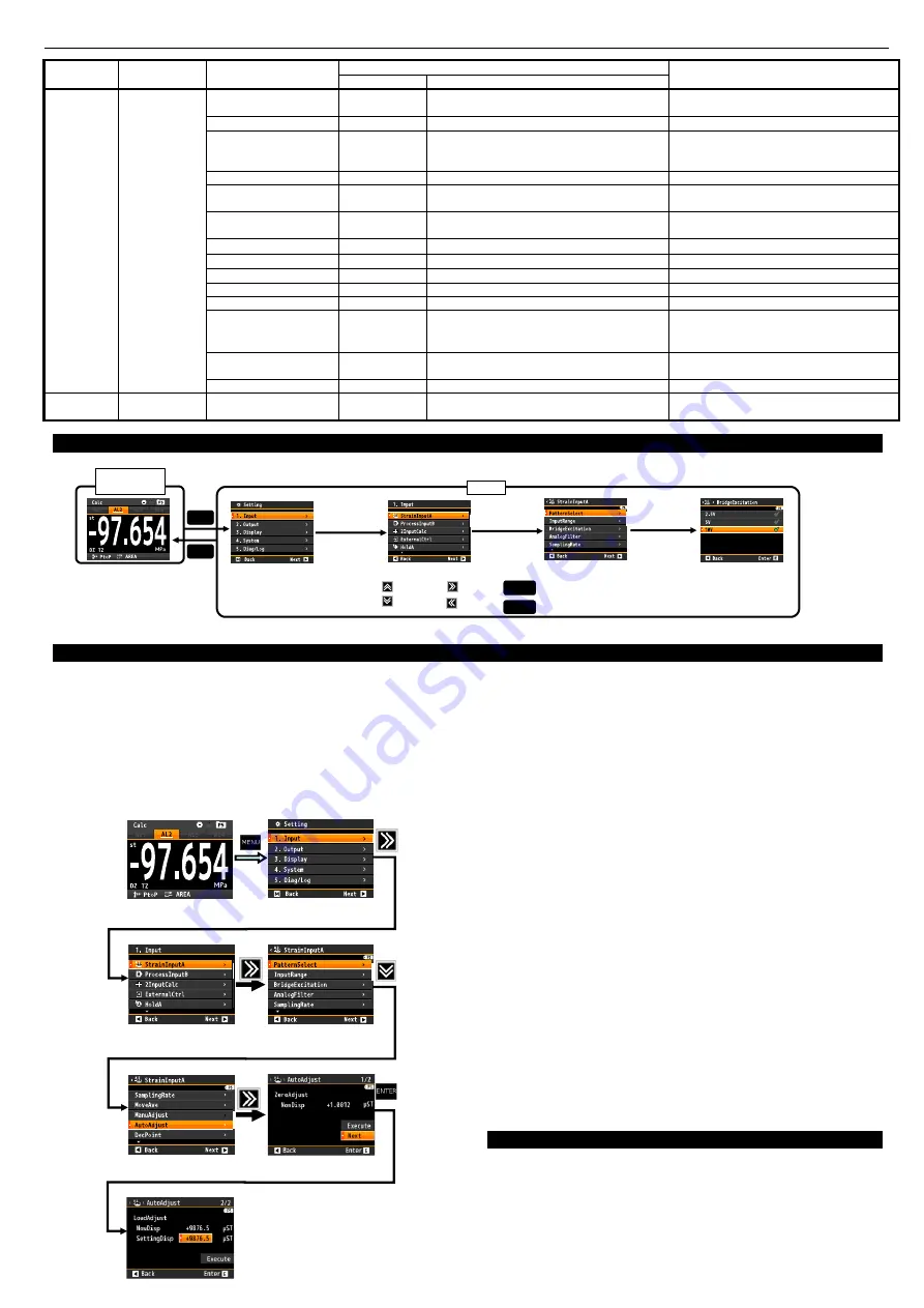
Basic operations for setting displays are shown as below. The following is an example for changing the voltage of bridge power supply.
Measurement
Display
MENU
Setting
MENU
Up/Down
Next
Back
Caution:Settings are saved by pressing MENU key , so settings are not saved if power off in setting mode.
ENTER
MENU
Determine
Settings are saved and back to measurement display
Caution:Measuring continues with old settings in setting mode.(But external control is inactive.)
1
st
Layer
2
nd
Layer
3
rd
Layer
4
th
Layer
1. Input
Strain
InputA
Bridge
Excitation
9.
SETTING EXAMPLES
9-1.
Example of Calibrating of Straingauge Input
How to calibrate straingauge input are below.
9-1-1
.
AutoAdjust
①
Go to [AutoAdjust] display.
(Setting)→1.Input→StaringaugeA/B→AutoAdjust
②
How to operate in [AutoAdjust] display(0% calibration)
・
Calibrate input as 0% by [Execute] button.
(Check [NowDisp] → 0)
・
[Next] button.
③
How to operate in [AutoAdjust] display(span calibration)
・
Apply actual load to the sensor.
・
Set the input load value to "SettingDisp".
・
Select "Execute" and press "ENTER" key.
9-1-2
.
ManuAdjust
①
Go to [ManuAdjust] display.
(Setting)→1.Input→StaringaugeA/B→ManuAdjust
②
How to operate in [ManuAdjust] display(0% calibration)
・
Calibrate input as 0% by [Execute] button.
(Check [NowDisp] → 0)
・
[Next] button.
③
How to operate in [ManuAdjust] display(span calibration)
・
Set rated output value of sensor to “RateOutput”.
・
Select "Execute" and press "ENTER" key.
9-2.
Example of Calibrating of Process Input
①
Go to [Offset] display.
(Setting)→1Input→ProcessInputA/B→Offset
②
How to operate in [Offset] display(Near 0% calibration)
・
Get input value by execute [Read input val]. (You can
enter the value manually too.)
・
Enter DispValue manually that you want to display.
・
Back to one before by press left arrow key/
③
Go to [Fullscale] display.
(Near 100% calibration)
・
Operation is same as
②
.
*Settings are saved by pressing MENU key and back to
measurement display. Don’t power off until back to
measurement display.
10.
SETTING OF UNITS
Units are selectable and can be displayed optionally.
If units should be used is not available, custom units up to 6
characters are can be made.
*For custom units, please refer to the detailed manual which can
be downloaded from our home page.
1st Layer
2nd Layer
3rd Layer
(setting items)
4th Layer (setting values)
Remarks
Initial values
Initial values
1.Input
MultiA
S1
~
S4
MultiB
S1
~
S4
TimeoutOutput
None
None/AL1/AL2/AL3/AL4
DelayTimer
00.01
00.01
~
99.99[sec]
Enable if HoldStartCond. is StartDelay.
HoldType
None
None/PeakHold/BottomHold/AmpHold
/DevHold/MaximalHold/MinimalHold
/DifferenceHold/InfrectionHold
DevBaseValue
+10000
±99999
Enable if HoldType is DevHold.
DifValue
1000
99999
Enable if HoldType is MaximalHold,
MinimalHold, DifferenceHold.
DifMag
1.00
0.01
~
99.99[Times]
Enable if HoldType is MaximalHold,
MinimalHold, DifferenceHold.
InfTimeA
100
1
~
499[Sampling]
Enable if HoldType is InflectionHold.
InfTimeB
100
1
~
499[Sampling]
Enable if HoldType is InflectionHold.
InfValueZ
1000
±99999
Enable if HoldType is InflectionHold.
CompOutput
None
None/AL1/AL2/AL3/AL4
CompAlarmCond.
Outside
Outside/Inside
CompJudgeValue
LowerValue
:
0
UpperValue
:
10000
LowerValue
:
±99999
UpperValue
:
±99999
CompTiming
WithinSectio
n
WithinSection/EndOfSection
NoDetected
NoAlarm
NoAlarm/WithAlarm
3.Display
DispSelect
MultiSelect
ALL
MultiAValue/MultiAGraph
MultiBValue/MultiBGraph
[Input]
MENU key
(Measurement display)
1
st
Layer
2
nd
Layer
3
rd
Layer
3
rd
Layer
4
th
Layer
Serch
[AutoAdjust]
①[Excute]
②[Next]
[StrainInputA]
[AutoAdjust]
①Set [DispValue]
②[Execute]
Finish
4
th
Layer
①Set[SettingDisp]
②[Execute]


