background image

Please note that, owing to the scalding process, the temperature can fall by 

several degrees. The higher the set temperature, the higher the deviation.

Information

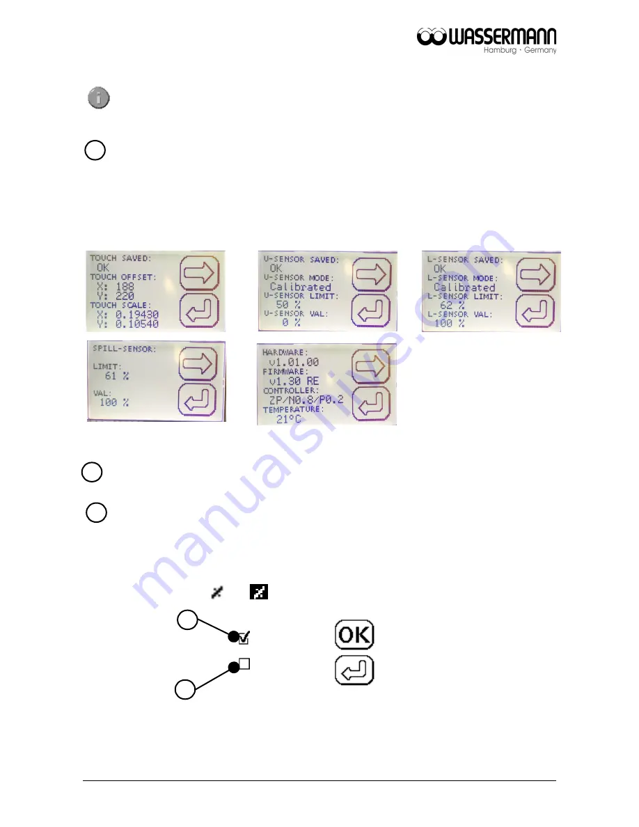
Here the parameters from the touch screen, sensors, hardware and software are 

displayed. 

„Back to start menu“

Automatic wax removal

The automatic wax removal process is conducted before or after the scalding process 

once a minimum temperature of 

80 °C

 has been reached. The removal/rolling mode is 

indicated by the symbol     . or   

if it is active. Parameters for rolling control. 

DEF

MAN

(a) Default: 3 min 

ON

 / 3 min 

OFF

.

(b) Manuel: 1-29 min 

ON

 / time-off = time-on.

18

17

a

b

15

16

Summary of Contents for Wapo-Ex 12 II

Page 1: ...Boil Out Unit Wapo Ex 12 II USER MANUAL...

Page 2: ...dents as well as the precautions given in this user manual We are not liable for any damages which occur due to inappropriate usage or faulty operation of this device Make sure that anyone using this...

Page 3: ...Cleaning the Wax Container at least 1x per week according to requirements 28 10 1 2 Changing the Water at least every 6 weeks according to requirements 28 10 1 3 Cleaning Procedure of the Combi Senso...

Page 4: ...ble and stands out thanks to its flexible usage programmable timer and automatic wax removal The electronic water level gauge the leakage signal and the inlet limitation ensure additional safety free...

Page 5: ...s in this user manual The equipment is designed only for its intended application WARNING Servicing and repairs should be carried out only by authorized specialists Disconnect the power plug before st...

Page 6: ...instructions Warranty and responsibility provisions contained in the sales and supply conditions of Wassermann Dental Maschinen GmbH are not extended by these instructions 5 Application The Wapo Ex 1...

Page 7: ...n level is above 470 mm Leave a side clearance of at least 50 mm at the right and the rear side of the unit to allow adequate heat circulation Tip Install the unit under an extractor hood to remove th...

Page 8: ...of a hose clamp to the outlet on the unit Make sure the hose it at a suitable height above the feeder pipe The minimum amount of water should be about 4 5 l min at a supply pressure of 1 5 max 6 bar...

Page 9: ...l parts in the large stainless steel basket Fit the spray arm on the connecting joint and swing it down bayonet connector Make sure all seals are clean Insert the channel from the front so that any sm...

Page 10: ...hat the mains and the unit operate on the same voltage Turn on the main switch green rocker switch Set the selector lever to the Automatic scalding position Touch on and water supply is activated or i...

Page 11: ...he symbol on the display The process must be ended manually Stop the process by pressing the symbol again Set the selector lever back to Automatic scalding again Wax remover only needs to be added as...

Page 12: ...ss This particularly applies to functions and The start menu Marking Set point temperature To the setup menu Heater inlet or roller on off Start scalding Menu automatic scalding Set up menu page 1 In...

Page 13: ...ate and time Forward at menu Work mode Information Back to start menu Set up menu page 3 Parameter roller Parameter inlet Forward at menu Water supply in manual operation Back to start menu 13 13 9 15...

Page 14: ...If the temperature falls below 66 C the process is canceled and the heating symbol appears Menu automatic scalding Define the parameters for scalding temperature and scalding duration By briefly tappi...

Page 15: ...to adjust the pre heat temperature of the program temperature This avoids long heat up or cool down phases The pre heat temperature may be up to 8 C higher than the program temperature for the program...

Page 16: ...adjusted to the conductance of the water How it works Pump out water The water level drops to below the sensor Evaluate temperature sensors values Water fills until the upper sensor is well covered by...

Page 17: ...d a Unit heats up to the temperature programmed under plus tolerance to compensate for heat loss through the conveying pump After reaching this value the result measured is validated by a control cycl...

Page 18: ...s hardware and software are displayed Back to start menu Automatic wax removal The automatic wax removal process is conducted before or after the scalding process once a minimum temperature of 80 C ha...

Page 19: ...e water supply runs for 10 seconds when the temperature is less than 78 C If the temperature is higher than 78 C the water supply runs until reaching the upper sensor There are two further parameters...

Page 20: ...ON Function Filling before entering sleep Allows refilling before entering sleep Filling before entering Sleep ON OFF Default ON Function Filling during waxscalding Allows refilling during waxscalding...

Page 21: ...10s 199s sum of all ON times c Constant constant water supply of 10s 199s adjustable Factory setting CONST 60 sec In order to be on the save side we have programed 60 seconds of water supply from the...

Page 22: ...y has to be confirmed by tap the symbol Operating the pump without water may cause the pump to fail Turn off the pump when it is air suctioning Remove the residual water with the valve on the bottom o...

Page 23: ...idelines The Wapo Ex 12 II is protected against running dry if the water is too low A warning signal also sounds if the water level is too low An additional safeguard protects the heater against overh...

Page 24: ...tarted by the or symbol After the scalding process has ended the temperature falls rises to the pre set temperature again 8 3 Manual Spray Head To manually scald using the spray the selector lever mus...

Page 25: ...w function since version V0143 Fault Cause Solution Wapo Ex 12 II does not heat Combi sensor v 2 is dirty Clean the combi sensor v 2 Wapo Ex 12 II does not heat although water level is ok and combi se...

Page 26: ...ile the logo of Wassermann appears please contact the touch display two times Then you will reach the self explanatory touch panel calibration Fig 1 2 Screen protector damaged Please contact our servi...

Page 27: ...eaner Use only cold cleaners to avoid damaging the paintwork or removing the lettering The unit should be cleaned at regular intervals to ensure trouble free operation Clean the outside of the unit wi...

Page 28: ...or is hanging in wash basin Set function switch to Pump down Switch on the pump by touching the symbol The combi sensor is automatically cleaned by the cleaning nozzle also see 8 1 3 After pump down s...

Page 29: ...s step While pumping down the water out of the system a small part of the flow goes through the nozzle and is cleaning the sensor with a spray of hot water Be sure that the cleaning procedure drain mo...

Page 30: ...bi Sensor v 2 if it is very dirty according to requirements 30 4x M5 unscrew the nuts Pull off the sensor plug 6 pin Remove the combi sensor v 2 The combi sensor v 2 REF 170323 is located below the cl...

Page 31: ...door in the side cover Dismount the combi sensor v 2 Use hot steam for cleaning Mount the combi sensor v 2 reconnect the sensor plug 6 pin correctly 31 Upper sensor U Max filling height Temperature s...

Page 32: ...ow or breathe in lime remover Otherwise seek medical help 10 2 Maintenance The unit does not require any servicing Just make sure that the device is kept clean Warning Please check the leak tightness...

Page 33: ...0230 830235 Accessories Item no Service set 1 L lime remover and 2 L wax remover 170330 10 7 Warranty The warranty period for our equipment is 12 months If faults occur within the warranty period cont...

Page 34: ...the Unit The unit has to be disposed by an authorized recycling operation The selected company has to be informed of all possibly health hazardous residues in the unit 12 1 Information on Disposal for...

Page 35: ...Richtlinien entspricht Diese Erkl rung wird ung ltig falls die Maschine ohne unsere Zustimmung ver ndert wird This is to confirm that the above mentioned machine complies with the described EU guidel...

Page 36: ......

Reviews: