Centering
Product Reference Guide
3-13
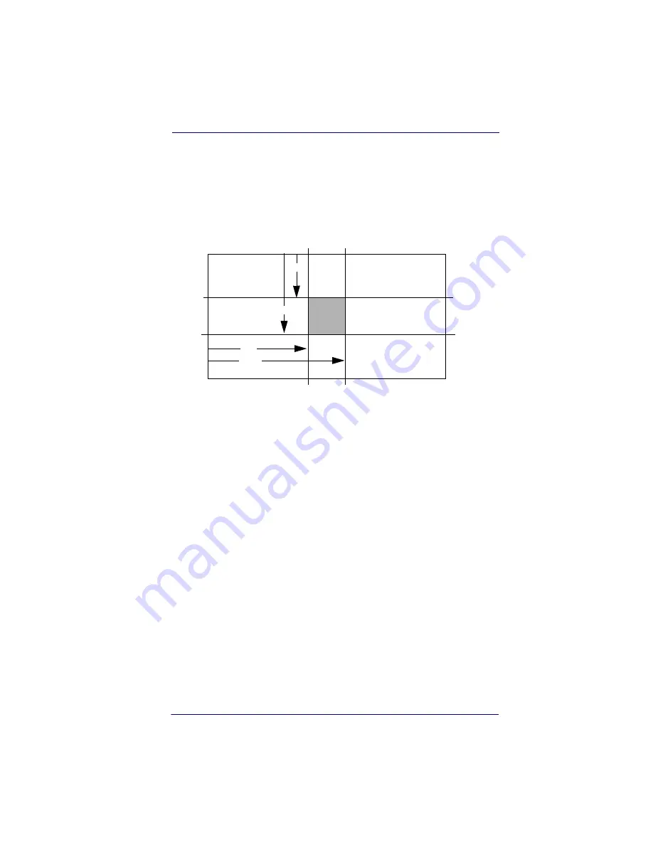
In the example in
, the gray area is the full imager field of view
and the white area is the centering window. Bar Code 1 will not be read,
while Bar Code 2 will be.The default centering window is a 128x96 pixel
area in the center of the imager’s field of view. The following diagram
illustrates the default top, bottom, left, and right pixel positions, mea-
sured from the top and the left side of the imager’s field of view, which is
640 by 480 pixels.
If a bar code is not within the predefined window, it will not be decoded
or output by the imager. If centering is turned on by scanning
Centering
On
, the imager only reads codes that intersect the centering window you
specify using the
Top
,
Bottom
,
Left
, or
Right
bar codes.
0
100%
100%
Default
Center
40%
60%
40%
60%
Left
Right
Bottom
Top
Summary of Contents for 2D
Page 1: ...P r o d u c t R e f e r e n c e G u i d e Wasp DuraLine 2D Imager Dura...
Page 24: ...Terminal Interfaces 2 12 DuraLine 2D Imagers NOTES...
Page 54: ...Data Editing 4 8 DuraLine 2D Imagers NOTES...
Page 110: ...Symbologies 6 50 DuraLine 2D Imagers NOTES...
Page 122: ...Imaging Commands 7 12 DuraLine 2D Imagers NOTES...
Page 140: ...OCR Programming 8 18 DuraLine 2D Imagers NOTES...
Page 152: ...Utilities 10 6 DuraLine 2D Imagers NOTES...
Page 180: ...Serial Programming Commands 11 28 DuraLine 2D Imagers NOTES...
Page 192: ...A 8 DuraLine 2D Imagers NOTES...
Page 196: ...B 4 DuraLine 2D Imagers OCR Programming Chart a e d g c h t l Discard Save r...
Page 197: ...Programming Chart User s Guide B 5 Programming Chart A C B F E D 1 0 2 3...
Page 199: ......
Page 200: ...2004 12 04...


