7
INSTALLATION
1.
Run some water from the hot and cold faucets to flush the
water lines and remove particles that might clog up the water
valve screens.
2.
Remove the inlet hoses and rubber washers from the plastic
bag and install the rubber washers in each end of the inlet
hoses.
3.
Carefully connect the inlet hose marked "HOT" to the outside
"H" outlet of the water valve. Tighten by hand, then tighten
another 2/3 turn with pliers. Carefully connect the other
inlet hose to the inside "C" outlet of the water valve. Tighten
by hand, then tighten another 2/3 turn with pliers.
Do not
crossthread or over-tighten these connections.
4. Connect the inlet hose ends to the HOT and
COLD water faucets tightly by hand, then
tighten another 2/3 turn with pliers. Turn the
water on and check for leaks.
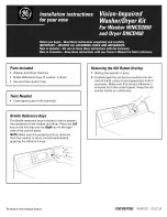
5.
On machines equipped with drain pump, form
a U shape on the end of the drain hose, with
the hose pointed toward the drain.
NOTE:
If the drain hose is placed in a standpipe
without forming a U shape, a siphoning action
could occur. There must be an air gap around
the drain hose. A snug hose fit can also cause
a siphoning action.
6. Carefully move the washer to its final location.
NOTE:
Do not use the dispenser drawer or door to lift washer.
7. With the washer in its final position, place a level on topo
f
the washer. Adjust the front leveling legs up or down to ensure
the washer is resting solid. Turn the lock nuts oneach leg up
towards the base of the washer and snug with a wrench.
NOTE:
Keep the leg extension at a minimum to prevent
excessive vibration. The farther out the legs are extended the
more the washer will vibrate. Rear leg adjustments are also
accessible through the front service panel.
8.
Models equipped with drain pump:
Place the formed end
of the drain hose in a laundry tub or a standpipe and secure
with the cable tie provided in the enclosure package.
NOTE
:
The drain pipe or floor drain, into which the drain hose is placed,
MUST
be at least 1/2 inch larger in diameter than the drain
hose. This will insure that the sewer line cannot back up into
the washing machine.
9. Plug the power cord into a grounded outlet.
NOTE:
Check to ensure the power is off at the circuit breaker/
fuse box before plugging the power cord into an outlet.
10.Turn on the power at the circuit breaker/fuse box.
11.Be sure you have read the "Important Safety Instructions"
before operating this washer.
12.Run the washer through a complete cycle. Check for water
leaks and proper operation.
13. Keep these instructions for future reference.
NOTE:
A wiring diagram is located inside the washer on the
side panel.
Cable
Tie