background image

WINCH MANUAL 

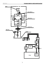
HYDRAULIC pRINCIpAL CHART AND INSTALLATION:

7

V1

V2

P

A

B

T

Hydraulic Motor

Winch

Balance Valve

Oil Tank

Engine

Relief Valve

Selector Valve

Oil Tank

Pump

Engine

Motor

Winch

Check  

Valve

Relief 

Valve

Control  

Valve

Oil Filter

Cooler

Summary of Contents for 13JR02H-CAD

Page 1: ...e operating the product Failure to do so could result in serious injury Specifications descriptions and images in this manual are as accurate as known at the time of publication but are subject to cha...

Page 2: ...that when you need to use it you can use it with confidence and safety Below is a list of the components of your winch and their uses 1 This winch is engineered for maximum line pull with only one lay...

Page 3: ...ands get within 12 30cm of the winch while re spooling Turn off the winch and repeat the procedure until a few feet of cable is left Disconnect the remote control and finish spooling by hand by rotati...

Page 4: ...be followed to reduce the risk of personal injury and damage to the equipment Read all these instructions before using this tool WARNING Keep children away Children must never be allowed in the work...

Page 5: ...uld easily exceed the winch rating and snap the cable When the vehicle is parked on an incline you should use wheel chocks CAUTION Always re spool cable neatly after any operation this will avoid any...

Page 6: ...ides for the simultaneous flow of hydraulic fluid both into and out of the unit Hydraulic system pressure can be routed with the selector valve to operate the unit in either direction or a correspondi...

Page 7: ...c principal chart and installation 7 V1 V2 P A B T Hydraulic Motor Winch Balance Valve Oil Tank Engine Relief Valve Selector Valve Oil Tank Pump Engine Motor Winch Check Valve Relief Valve Control Val...

Page 8: ...ersing directions If you are using a heat exchanger with your application to cool the hydraulic fluid you should refer to the illustration about mounting You should check the hydraulic fluid level reg...

Page 9: ...r the winch hook is strictly prohibited Overhaul When the hydraulic winch doesnt work or has malfunctioned is confirmed the operator user can check and repair if qualified to do so in instances where...

Page 10: ...Agent may make reasonable charges for parts and or labour for repairs not covered by this Lifetime Limited Warranty None warrantable returns will be charged at BPE Solutions North America standard ra...

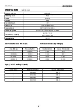
Page 11: ...410mm Net weight Ibs kg 771 6 350 Line Pull and Pressure First layer Line pull lbs kgs Pressure Mpa Psi 0 4 580 2 15000 6804 10 1045 4 20000 9072 15 2175 6 25000 11340 17 2465 6 29700 13500 19 2755 7...

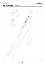
Page 12: ...Winch Manual SPECIFICATIONS 12 WINCH ASSEMBLY DRAWING 13JR02H CAD...

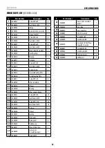
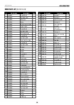
Page 13: ...8 Oil Seal 1 22 13JR0019 Bearing 1 23 13JR0020 Drum adapter flange 1 24 13JR0021 Screw M10 x 30 16 25 13JR0022 Lock Washer 10 16 26 13JR0023 Screw M12 x 110 16 27 13JR0024 Lock Washer 12 16 28 13JR002...

Page 14: ...15mm Net weight Ibs kg 903 8 410 Line Pull and Pressure First layer Line pull lbs kgs Pressure Mpa Psi 0 4 580 2 21000 9526 10 1450 4 23900 10841 12 1740 5 27700 12565 15 2175 6 33000 15000 18 2610 7...

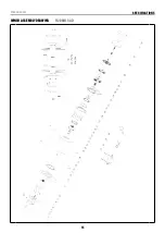
Page 15: ...Winch Manual SPECIFICATIONS 15 WINCH ASSEMBLY DRAWING 15JR02H CAD...

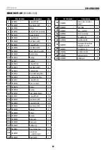
Page 16: ...8 Oil Seal 1 22 15JR0019 Bearing 1 23 15JR0020 Drum adapter flange 1 24 15JR0021 Screw M10 x 30 16 25 15JR0022 Lock Washer 10 16 26 15JR0023 Screw M12 x 100 16 27 15JR0024 Lock Washer 12 16 28 15JR002...

Page 17: ...1184mm 513mm 420mm Net weight Ibs kg 1135 515 Line Pull and Pressure First layer Line pull lbs kgs Pressure Mpa Psi 0 7 5 1087 8 22000 10000 10 1450 4 33000 15000 15 2175 6 44000 20000 20 2900 8 Layer...

Page 18: ...Winch Manual SPECIFICATIONS 18 WINCH ASSEMBLY DRAWING 20JR02H CAD...

Page 19: ...2 27 20JR0300 Drum Assembly 1 28 20JR0025 Transmission shaft 1 29 20JR0400 Drum adapter flange 1 30 20JR0026 Screw M12 x 35 14 31 20JR0027 Lock Washer 12 14 32 20JR0028 Screw M14 x 110 16 33 20JR0029...

Page 20: ...261mm 640mm 540mm Net weight Ibs kg 1940 880 Line Pull and Pressure First layer Line pull lbs kgs Pressure Mpa Psi 0 7 1015 3 22000 10000 8 5 1232 8 44000 20000 15 2175 6 55000 25000 18 2610 7 Layers...

Page 21: ...Winch Manual SPECIFICATIONS 21 WINCH ASSEMBLY DRAWING 25JR02H CAD...

Page 22: ...Drum Assembly 1 25 25JR0022 Transmission shaft 1 26 25JR0400 Drum adapter flange 1 27 25JR0023 Screw M12 x 35 8 28 25JR0024 Lock Washer 12 8 29 25JR0025 End cap II 1 30 25JR0026 Oil Seal 1 31 25JR0027...

Page 23: ...276mm 640mm 540mm Net weight Ibs kg 2083 945 Line Pull and Pressure First layer Line pull lbs kgs Pressure Mpa Psi 0 7 1015 3 44000 20000 11 1595 4 55000 25000 14 2030 5 66000 30000 16 2320 6 Layers L...

Page 24: ...Winch Manual SPECIFICATIONS 24 WINCH ASSEMBLY DRAWING 30JR02H CAD...

Page 25: ...Drum Assembly 1 25 30JR0022 Transmission shaft 1 26 30JR0400 Drum adapter flange 1 27 30JR0023 Screw M12 x 35 8 28 30JR0024 Lock Washer 12 8 29 30JR0025 End cap II 1 30 30JR0026 Oil Seal 1 31 30JR0027...

Page 26: ...support warriorwinches com For warranty and repair enquiries please contact the retailer where you purchased your winch product...

Reviews: