background image

AmurAct                                             AMURACT_IOM_RevK_0415

7

Factory default configuration of the five dipswitches is shown below. 

Switch #1 

Factory default - ON 

An increasing control 


signal causes the valve stem to drive up, opening


a two-way valve, or opening the L (lower) port and 


closing the U (upper) port of a three-way valve. The


valve stem will drive down upon loss  of  signal. When 


Switch 1 is  in the OFF position an increasing control 


signal causes the valve stem to drive down, closing a


 two-way valve, or closing the L (lower) port and opening the U (upper) port of a three way valve. The valve stem will drive up 
upon loss of signal.

Switch #2 

Factory default - ON 


Upon loss of power the Enerdrive® circuit will drive the valve stem down, closing a two-way 

valve, or closing the L (lower) port and opening the U (upper) port of a three-way valve. When Switch #2 is in the OFF position, 
upon loss of power the Enerdrive® circuit will drive the valve stem up, opening a two-way valve or opening the L (Lower) port 
and closing the U (upper) port of a three-way valve.

Switch #3 

Factory default - ON 


The motor will accept a 4-20 mAdc control signal connected to terminals 1(-) and 3(+) on 

terminal block 1. When Switch #3 is in the OFF position the  motor will accept a 2-10 vdc signal.

Switch #4 

Factory default - OFF   The motor will provide a 4-20 mAdc feedback output at terminals 1(-) and 5(+) on terminal 
block 1. When Switch #4 is in the ON position the motor will provide a 2-10 vdc output.

Switch #5 

(2-Way) Factory default - ON 

This establishes a linear relationship between the control signal and valve stem lift. When 

Switch #5 is in the OFF position a “non-linear” relationship is established between the control signal and valve stem lift. This is 
uniquely applicable only on 3-way valve linkages.


(3-Way) Factory default - OFF  The 3-way linkage has a different signal to lift relationship and should not use the linearization 
feature. For 3-way valves, switch #5 should always be OFF.

DIPSWITCHES

Switch #1: Action & 
                      Signal Loss

Switch #2: Power Fail

Switch #3: Signal

Switch #4: Feedback
Switch #5: Linearization

CONFIGURATION OF DIPSWITCHES
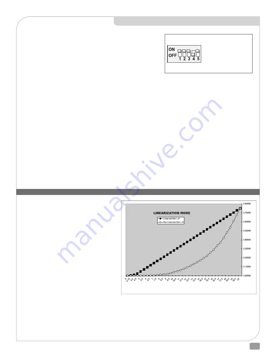
mA Signal 

St

em L

ift


Placing dipswitch #5 in its ON (Linearizing) position 
accomplishes several objectives that may be helpful in 
specific control valve installations. One result is that the 
entire input signal range is applied to modulating the valve 
opening. Only at the very end of the signal range does the 
AmurAct linkage drive into lockup. Another result is that 
the inherent characteristic of the control valve is preserved.  
“Linearizing” operation can provide linear flow control 
when using a valve having linear trim.

Placing dipswitch #5 on its OFF (Non-Linear) position causes 
the valve stem to rise very slowly in the beginning of its 
stroke, and to rise increasingly rapidly as the valve opens. 
This mode uses the first 25% of the control signal to move 
the linkage into and out of lockup. “Non-Linear” operation 
may be useful when additional control is needed at low 
flow rates, and additional response is required for changes 
in higher flow rates. 

Selection of the linearization mode (dipswitch #5) can be 
made during operation, and dipswitch #5 should be left in 
the position that produces the better system control result.

FOR 2-WAY ONLY

Summary of Contents for AmurAct Linkage LS Series

Page 1: ...3 way valves Otherwise in all other circumstances the Linear Stem Lift factory default will be the desired setting In either case correct control valve sizing is critical to good operation See indivi...

Page 2: ...e and applies it to the input shaft of the second component the AmurAct linkage The link age converts rotary force and motion to linear force and motion to operate the reciprocating stem of an attache...

Page 3: ...ECTORisthreadedontothevalvestemandattachedto the LEVER by two connecting links Upward movement of the LEVER draws the VALVE STEM upward The articulated link connection reduces side loading on the valv...

Page 4: ...or you must first follow steps 1 5 of this procedure and when finished perform the Auto Calibration procedure on page 8 Failure to remove power AND de energize the Enerdrive system first prior to de c...

Page 5: ...15 mA Slow Blow with T41 terminations Contact the factory at 610 317 0800 before attempting to reconfigure or reposition an AmurAct actuator Improperly rotating the linkage on the valve bonnet adverse...

Page 6: ...may not shut off tightly The control signal maximum must reach 20 00 mAdc If the control signal maixmum does not reach 20 00 mAdc the actuator may not reach its end of travel in that direction and the...

Page 7: ...tionship between the control signal and valve stem lift When Switch 5 is in the OFF position a non linear relationship is established between the control signal and valve stem lift This is uniquely ap...

Page 8: ...ress the RESET pushbutton or vary the control signal These actions may result in the actuator programming being changed If the actuator progamming is changed the actuator may not respond correctly to...

Page 9: ...sition ______________________________________ 6 If the same motor is to be reinstalled proceed to step 7 If it is to be replaced label field wires for reconnection then discon nect and remove them ___...

Page 10: ...before applying a control signal Important A small phase error in re clamping the motor without initiating an AUTOSTROKE CALIBRATION CYCLE will cause severe damage to the motor by overrunning the cycl...

Page 11: ...ct with the top jam nut _______________________________________ 3 Lower the linkage assembly over the valve stem and bonnet then slide the bonnet nut over the connector and loosely thread the nut onto...

Page 12: ...d linkage and full seating force is now present on the valve plug LEAVE THE CLAMP IN PLACE UNTIL MOTOR INSTALLATION IS COMPLETE ________________________________________ 8 Calibrate and install the mot...

Page 13: ...bration is complete push the crank firmly against its support column to fully extend the linkage input shaft Install a clamp onto the lower end of the crank and the crank support column Draw the crank...

Page 14: ...ose off force Remember to press the motor RESET pushbutton after installation and calibration are complete and the motor is energized but before the system is placed into service Verify Dip Switch 5 i...

Page 15: ...is installed correctly 10 Initate an AUTOSTROKE CALIBRATION CYCLE STOP You must wait for the AUTOSTROKE CALIBRATION CYCLE to finish before going on to the next step 11 Reset the actuator programming...

Page 16: ...F WARREN CONTROLS INCORPORATED THIS DRAWING IS FOR REFERENCE PURPOSES ONLY POSSESSION OF IT DOES NOT IN ITSELF CONVEY ANY RIGHT OR LICENSE TO MAKE MANUFACTURE USE AND OR SELL THE DEVICE PROCESS METHOD...

Page 17: ...AmurAct AMURACT_IOM_RevK_0415 17 D3400007...

Page 18: ...F WARREN CONTROLS INCORPORATED THIS DRAWING IS FOR REFERENCE PURPOSES ONLY POSSESSION OF IT DOES NOT IN ITSELF CONVEY ANY RIGHT OR LICENSE TO MAKE MANUFACTURE USE AND OR SELL THE DEVICE PROCESS METHOD...

Page 19: ...AmurAct AMURACT_IOM_RevK_0415 19 D3400011...

Page 20: ...F WARREN CONTROLS INCORPORATED THIS DRAWING IS FOR REFERENCE PURPOSES ONLY POSSESSION OF IT DOES NOT IN ITSELF CONVEY ANY RIGHT OR LICENSE TO MAKE MANUFACTURE USE AND OR SELL THE DEVICE PROCESS METHOD...

Page 21: ...AmurAct AMURACT_IOM_RevK_0415 21 D3400014...

Page 22: ...F WARREN CONTROLS INCORPORATED THIS DRAWING IS FOR REFERENCE PURPOSES ONLY POSSESSION OF IT DOES NOT IN ITSELF CONVEY ANY RIGHT OR LICENSE TO MAKE MANUFACTURE USE AND OR SELL THE DEVICE PROCESS METHOD...

Page 23: ...AmurAct AMURACT_IOM_RevK_0415 23 D3400015...

Page 24: ...Act Actuator Linkage and Motor AMURACT_ IOM_RevK_0415 92500060 Rev K 2600 EMRICK BLVD BETHLEHEM PA 18020 USA 800 922 0085 WWW WARRENCONTROLS COM DEPENDABLE RUGGED PRECISION CONTROL VALVES AND ACCESSOR...

Reviews: