background image

Auger Bearings and Auger Shafts 

     The auger bearings (PART #PU-UCF204-12) are a sealed unit and do not require 
lubrication. To replace the top auger all the fuel must be removed from the hopper, as well as 
the top auger motor assembly (see above). Once this is done the four bolts that hold in the 
bearings can be removed. At this time, the complete auger assembly can be 
pulled from the stove. Loosen the two (2) set screws with a 9/64” allen wrench, which will 
disconnect the bearing from the shaft.  The bearing and auger shaft can be replaced by 
reversing this procedure.  When placing the auger bearing and shaft assembly back into the 
unit, always tighten the four bolts in a diagonal pattern to assure the bearings are aligned 
properly. Follow the same procedure to work on the bottom auger, with the exception that the 
pellets do not have to be removed from the hopper. 
 

Convection Blower 

 The convection blower (room air blower) — PART #BM-1376 — is located under the burn 
pot of the unit and can be removed by disconnecting the power leads and removing the four 
screws. Once this is done, the blower should slide out the rear of the unit. Reverse this 
procedure to install a new room air blower. 
 

Combustion Blower 

     To clean or replace the combustion (exhaust) blower — PART #PU-076002 — the power 
leads and the pellet vent pipe must be disconnected. Next, remove the four screws that hold 
the blower to the steel exhaust tube and the entire blower should release from the stove. The 
blower impeller, blower tube and the steel blower exhaust tube on the stove should be 
brushed and vacuumed. When cleaning or replacing the blower a new gasket should be 
added between the blower flange and the steel exhaust tube. 
 

Gaskets 

     This unit comes with a 3/4” rope gasket around the door, which should be replaced every 
two years. To replace the door gasket (Part #AC-DGKC), the old gasket must first be 
removed entirely — this may require you to scrape the old material from the channel before 
adding the new cement. Once this has been done the door should be closed and latched for 
twenty-four hours to allow the adhesive to harden. If you are replacing the window gasket 
(PART #AC-GGK), the new gasket already has adhesive on it. Remove the paper on the 
adhesive side and place the gasket around the outside edge of the glass, by forming a “U” 
with your fingers and running the new material around the window. The door and window 
gasket can be ordered from your local dealer or from the factory. 
 

Finish 
 

     This new unit has been painted with 1200 degree Metallic Paint (PART #AC-MCSP) that 
will retain its original look for years. If the unit should get wet and rust spots appear, they can 
be sanded with plain steel wool and repainted. We recommend this paint, as others may not 
adhere to the surface or withstand the high temperatures.

Glass 

     This unit has a 9” x 9” ceramic glass (Part #AC-G9) in the viewing door. If this glass 
becomes cracked in any area, the unit should be shut down and the window replaced. The 
glass can be ordered from your dealer or from the factory. 


You may order parts and options on our web site:  

www.englandsstoveworks.com

 ,  

or by calling (800) 516-3636.   

Our web site also offers service instructions that can be printed or viewed as video.

Summary of Contents for 25-PAF

Page 1: ...ding and fire codes Please read this entire manual before installation and use of this pellet fuel burning add on furnace Keep children furniture fixtures and all combustibles away from any heating ap...

Page 2: ...guide on our web site we have always tried to help our customers stay heat ready especially when oil and electricity prices continue to skyrocket Please look at our vast Help section on our web site...

Page 3: ...k the exhaust system 10 Keep pellets and all other combustible materials a safe distance from the stove 11 This unit will require floor protection if it is installed on a combustible surface The minim...

Page 4: ...lings Check local codes in your area This unit is equipped with a negative draft system that pulls air through the burn pot and pushes the exhaust out of the dwelling If this unit is connected to a fl...

Page 5: ...e thimble or pipe will be either six inches 6 or eight inches 8 and the proper reducer 3 to 6 or 3 to 8 can be purchased or ordered by your local dealer Connect a three inch 3 tee with clean out to th...

Page 6: ...bs total 3 Close hopper lid and secure the latches 4 Place a handful of pellets in the burn pot spread a small amount of fire starter over the top and ignite the pellets Wait a few minutes before clos...

Page 7: ...for more than 18 minutes the unit will have to be re started completely see Start Up Procedure NOTE The unit will also shut down in the event of Combustion Blower failure if this is the case the unit...

Page 8: ...ove the burn pot assembly clean it thoroughly and re install it refer to Exploded View this will require new gasket for the burn pot Be sure to tighten the set screws when you replace them but do not...

Page 9: ...blower exhaust tube on the stove should be brushed and vacuumed When cleaning or replacing the blower a new gasket should be added between the blower flange and the steel exhaust tube Gaskets This uni...

Page 10: ...r exit Thirty gauge or thicker pipe should run from the top of the furnace to the hot air trunk line of your existing hot air system Using the least possible amount of pipe will help the heat transfer...

Page 11: ...I D Pipe see manual 3 Min NOTE 1 If 3 flue pipe exceeds 15 in length increase to 4 flue pipe for remaining flue connections 2 Total flue length should not exceed 35 3 Horizontal run not to exceed 4 4...

Page 12: ...Low Burn Heat Range setting 1 Room Air Blower setting 1 Medium Low Heat Range setting 2 3 Room Air Blower setting Medium High Heat Range setting 5 8 Room Air Blower setting High Burn Heat Range settin...

Page 13: ...d on our pellet units as long as it is a 24 volt that works with millivolt systems After unplugging the unit locate the jumper wire J 18 on the bottom of the control panel The two screws should then b...

Page 14: ...curs because of an accident improper handling improper operation improper installation abuse or unauthorized repair made or attempted to be made The manufacturer is not liable for indirect incidental...

Page 15: ...1376 850 CFM CONVECTION BLOWER PU CB98 DIGITAL CONTROL BOARD PU 62 40 151 2 Hopper Lid Latch 2002 and later Models for earlier models order PU 103 50 PU AF6T TOP AUGER SHAFT W FLIGHTING PU AF11B BOTTO...

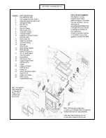
Page 16: ...Pellet Stove Exploded View...

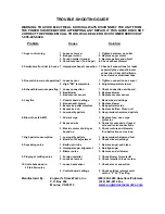
Page 17: ...oard settings 1 Review board settings 2 Bad exhaust blower 2 Replace blower 3 Excessive pellet moisture 3 Keep pellets inside 4 Excessive ash 4 Remove baffles Clean unit 5 Low quality pellets 5 Use pr...

Page 18: ......

Page 19: ...s _________________________________________________________ City ________________________ State __________ Zip _________________ UNIT INFORMATION Model Number _____________________ Purchase Date _____...

Reviews: