MCS2000-PSDRV2 Power Supply/Dual
Voltage/Dual Channel Driver
Installation & Operating Instructions
819-0525P-2010-7
Page 1: ...MCS2000 PSDRV2 Power Supply Dual Voltage Dual Channel Driver Installation Operating Instructions 819 0525 P 2010 7 ...
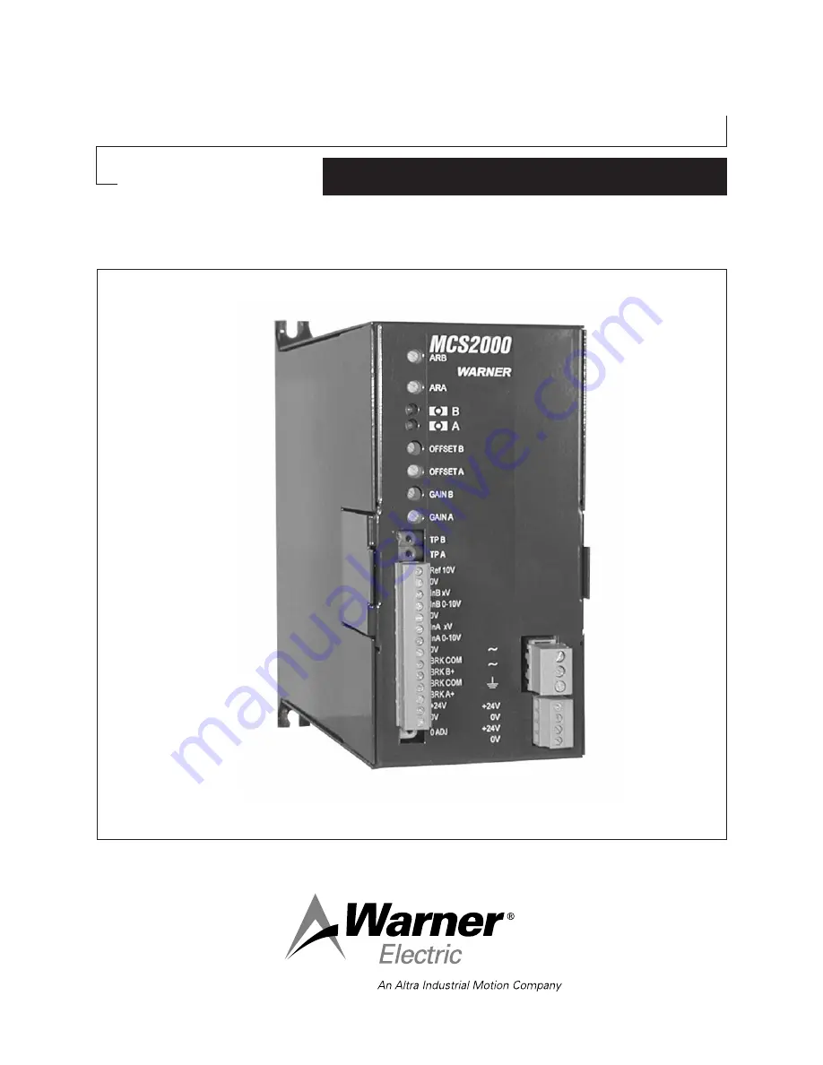
Page 2: ...2000 controllers offered as either a single channel system or dual channel system The MCS2000 ECA MCS2000 CTDA or MCS2000 CTLC controllers can provide the operating signals The MCS2000 PSDRV2 has reduced input terminals on the front of the unit for the driver section that are pluggable which will make installation and wiring much easier than the previous versions By using a pluggable terminal bloc...
Page 3: ... input power supply voltage Adjustable for each channel 2 4 volts DC with 24 VDC power supply input 4 8 volts DC with 48 VDC power supply input Analog Input Voltage 0 to 10 Volts DC on Input A or Input B When operating with 48 volt DC power input of 0 to 5 volts corresponds to 24 Volt DC output and from 5 to 10 volts input overvoltage mode from 24 to 48 volts DC with timed limitation Status and Di...
Page 4: ...r 10 screws mount the unit to the panel or mounting surface Tighten screws sufficiently so that unit will Figure 1 Mounting Dimensions Driver Outline and Mounting Dimensions not come loose during normal machine operation or vibration Note 0 Volt terminals in control are tied to control housing A good ground is required between the control and the panel or mounting surface o 3 After unit is mounted...
Page 5: ...A Manual for exact terminal strip locations and designations o 1 Connect a wire from terminal Out 1 V on the MCS2000 ECA to terminal number 1 InA 0 10 V on the MCS2000 PSDRV2 Insure that both terminals are tightened securely o 2 Connect a wire from terminal Out 1 0V on the MCS2000 ECA to terminal number 2 0V on the MCS2000 PSDRV2 Insure that both terminals are tightened securely If a dual brake sy...
Page 6: ...rounding out does not occur Note Refer to the MCS2000 CTDA or MCS2000 CTLC Manual for exact wire functions and designations Refer to Figure 3 for wiring hook ups green red MSC2000 PSDRV2 A Antiresidual Channel A B Antiresidual Channel B 1 2 3 4 5 6 7 8 9 10 InA 0 10V 0 V InB 0 10V 0V Brk A Brk A Brk B Brk B DC Pwr 24 48V 24V 24V 0V 0V MCS2000 ECA Controller MCS2000 PSDRV2 Driver Figure 2 MCS2000 E...
Page 7: ...wire Channel 2 Out V from the connector cable on the MCS2000 CT controller to terminal 3 In B 0 10 V on the MCS2000 PSDRV2 Insure that the terminal on the MCS2000 PSDRV2 is tightened securely o 4 Connect the black wire Channel 2 Out 0V from the connector cable on the MCS2000 CT controller to terminal 4 on the MCS2000 PSDRV2 Insure that the terminal on the MCS2000 PSDRV2 is tightened securely o 5 T...
Page 8: ...d 6 of the MCS2000 PSDRV2 Make sure the terminals are securely tightened o 2 If a brake is to be used on Channel B wire the brake to the Channel B terminals 7 and 8 on the MCS2000 PSDRV2 Make sure the terminals are securely tightened o 3 Wire AC power hot neutral and ground to the power input terminals on the right side of the MCS2000 PSDRV2 Make sure terminals are securely tightened Note Warner E...
Page 9: ...48 Volt Systems o 1 Wire the positive side of the 48 volt DC power supply to terminal 10 of the MCS2000 PSDRV2 Make sure that the terminal is securely tightened on the MCS2000 PSDRV2 o 2 Wire the negative side or DC common of the 48 volt DC power supply to terminal 9 of the MCS2000 PSDRV2 Make sure the terminal is securely tightened on the MCS2000 PSDRV2 Note Make sure the current capacity is suff...
Page 10: ...ATTB ATTC 25 ATTB ATTC 55 ATTB ATTC 115 All MTB s up to 12 magnets Up to 16 magnets if outputs paralleled MPB MPC2 MPB MPC15 MPB MPC70 MPB MPC120 MPB240 POB POC 0 3 to 20 s PRB H s 1 2 to 20 s PTB s 2 5 to 20 s PMC A s 10 to 40 s PHC R 0 6 to 40 s POB POC 40 80 if output and inputs paralleled Figure 5 48 Volt System Power Supply and Brake Wiring 48 Volt DC Power Supply MCS2000 PSDRV2 Driver When 1...
Page 11: ...Channel A input o 4c Using a small screwdriver rotate the anti residual potentiometer A fully counter clockwise so the output voltage to the brake is zero level Voltage can be measured to the Channel A brake on terminals 5 and 6 of the MCS2000 PSDRV2 Terminal 5 is positive and terminal 6 is negative Note that the GREEN LED for Channel A is flashing at this time o 4d Now slowly adjust the anti resi...
Page 12: ...minals 7 and 8 of the MCS2000 PSDRV2 Terminal 7 is positive and terminal 8 is negative Note that the GREEN LED for Channel B is flashing at this time o 5d Now slowly adjust the anti residual potentiometer B clockwise while feeling the reaction on the brake When the optimum anti residual output is obtained the brake will be very free to rotate or the armatures in the case of the TB s will feel like...
Page 13: ...utput current being supplied to the brake o 11 If other LED indications are present proceed to the troubleshooting section on page 17 to determine cause and appropriate action to take 48 Volt System o 1 Prior to applying power double check all wiring between Tension Control and Driver Driver and Brake or Brakes and 48 Volt Power Source and Driver o 2 Once connections are checked and confirmed that...
Page 14: ...Voltmeter connect the positive lead to terminal 3 and the negative lead to terminal 4 of the MCS2000 PSDRV2 for Channel B input o 5b Adjust the Tension controller being used to give a 0 VDC reading on the Channel B input o 5c Using a small screwdriver rotate the anti residual potentiometer B fully counter clockwise so the output voltage to the brake is zero level Voltage can be measured to the Cha...
Page 15: ...z frequency with the LED on for typically 0 5 second and off for 1 5 seconds This indicates the brake is operating in the overcurrent mode and will be limited to 60 seconds o 6b Allow the control to operate in this mode for 60 seconds or more and observe the LED s After the Overexcitation circuit times out the RED LED will be flashing at a frequency of approximately 30 hertz with the LED being ON ...
Page 16: ...g in the overcurrent mode and will be limited to 60 seconds o 9b Allow the control to operate in this mode for 60 seconds or more and observe the LED s After the overexcitation circuit times out the RED LED will be flashing at a frequency of approximately 30 hertz with the LED being ON approximately 1 second and OFF approximately 1 second Measuring the output to the brake on Terminals 5 and 6 shou...
Page 17: ...d channel can have a completely different set of indications This will be dependent on how controller is set to operate the MCS2000 PSDRV2 Driver System Troubleshooting Troubleshooting the MCS2000 PSDRV2 Dual Channel Dual Voltage Driver is fairly straight forward There are certain basic checks that can be made using a digital meter All readings taken on the MCS2000 PSDRV2 will be either DC voltage...
Page 18: ...5 Sec OFF 1 5 Sec ON 0 5 Sec OFF Short Circuit or Overload on Output at Power Up Output Locked OFF Driver has tripped Reset by Power Off and then Power On Short Circuit or Overload during normal operation Output Locked OFF Driver has tripped Reset by Power Off and then Power On Internal auxiliary power supply out of tolerance Output Locked OFF Auto Reset when condition clears Internal auxiliary po...
Page 19: ...nding and can engage properly Check that the input signal to the Channel A and Channel B inputs goes to full 10 volts on the control inputs If inputs do not go to 10 volts maximum check the controller for proper operation and set up Refer to the particular control manual for proper adjustments Brake seems to drag when off Check that the anti residual output is set properly Too little output and th...
Page 20: ...nal 7 Terminal 8 Terminal 5 Terminal 6 Terminal 10 Terminal 9 The following chart shows a comparison of the MCS2000 PSDRV MSC2000 PSDRVH and the MCS2000 PSDRV2 terminal connections These only apply to the Driver portion of the pluggable terminal block The Power Supply section between the three versions are the same and did not change If problems arise that are not covered in the above troubleshoot...
Page 21: ...Dimensions 4 Figure 2 MCS2000 ECA to MCS2000 DRV2 Wiring 6 Figure 3 MCS2000 CTxx to MCS2000 DRV2 Wiring 7 Figure 4 24 Volt Power and Brake Wiring 9 Figure 5 48 Volt Power and Brake Wiring 10 Figure 6 LED Indicator Operations and Descriptions Normal 17 Figure 7 LED Indicator Operations and Descriptions Faults 18 ...
Page 22: ...lation operation or maintenance Some states do not allow limitation on how long an implied warranty lasts so the above limitation may not apply to you Warner Electric LLC s obligation under this warranty is limited to the repair or replacement of the defective product and in no event shall Warner Electric LLC be liable for consequential indirect or incidental damages of any kind incurred by reason...