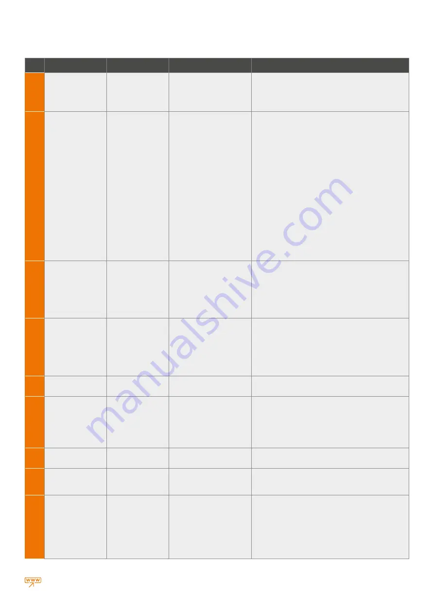
background image

33

warmhaus.com

Error

Code

Description of the Error

Malfunction

Probable Cause

Solution(s)

E 74

Second CH temperature 

Probe faulty

Boiler does not work,

E74 error code flashing on

the screen

> FLOW and LIMIT Sensor (double 

NTC ) faulty

1-) Call for authorised service at first

2-) Check CH temperature probe ressistance (double CH ntc probe is 

used as high temperature limit device) according to page 94 at section 

4.29 if its out of tolerance replace double NTC

3-) Check cabeling and connectors between double NTC and board
4-) Reset & Restart boiler

E 77

Absolute current values

reached

Boiler does not work,

E77 error code flashing on
the screen

> Gas inlet pressure

> Aging or rust on the electrode

> Recirculation on fluegas path
> Blokage on flue or wrong flue
> Electrode position
> Cabeling disconnections

> Combustion calibration

> Electronic board
> Gas valve failiure

1-) Call for authorised service at first

2-) Check gas supply pressure must be 20-17 mBar. Gas pressure must 

be in between on this values while boiler on operational
3-) Check wrong flue OR flue gas blockage
4-) Check recirculation ( flue gas leak ) from flue gas path to fresh air 
side, check flue gas sealings specially

5-) Check any problems on the ionisation electrode, (like condensation, 

rust etc.), and control poistioning of the electrode, if electrode poistion 
wrong calibrate electrode according to user manual page 118 or 119
6-) Check if the heat exchanger coils clogged or not

7-) Check for condensation on the cabling AND/OR on board
8-) Check earth connection between board and electrode

9-) Check electrode cabeling between board and electrode
10-) Check combustion CO2 or O2 values on HI and LO mode at sweeper 
mode according to direction of manual page 67- 70

11-) Perform Auto Calibration according to page 76 or 77
12-) If fault still persists Replace board, but use original service key 

from the board dismantled to keep original parameters and calibration 
points. If original service key not used aslo adjust P15 releated to the 
default value of boiler power and perform Au-To calibration according 

to page 76 or 77
13-) if not successfull replace gas valve, and Perform Au-To calibration 

according to page 76 or 77 Attention: Only authorised service must 
perform Au-To calibration

E 78

Max regulation current 
value reached

Boiler does not work,
E78 error code flashing on
the screen

> Gas inlet pressure
> Aging or rust on the electrode
> Recirculation on fluegas path
> Blokage on flue or wrong flue

> Electrode position
> Cabeling disconnections
> Combustion calibration
> Electronic board

> Gas valve failiure

1-) Call for authorised service at first

E 79

Min regulation current 
value reached

Boiler does not work,
E79 error code flashing on

the screen

> Gas inlet pressure
> Aging or rust on the electrode

> Recirculation on fluegas path
> Blokage on flue or wrong flue
> Electrode position
> Cabeling disconnections
> Combustion calibration
> Electronic board
> Gas valve failiure

1-) Call for authorised service at first

E 80

Problem on electronic gas
valve driver

Boiler does not work,
E80 error code flashing on
the screen

> Electronic board
> Gas valve failiure

1-) Call for authorised service at first

E 81

Lock-out for combustion
problem at starting (1)

Boiler does not work,
E81 error code flashing on

the screen

> Strong flue blokage
> Combustion problem

> Wrong flue
> Gas inlet pressure
> Aging or rust on the electrode
> Recirculation on fluegas path
> Electrode position
> Combustion calibration

1-) Call for authorised service at first

E82

Lock-out for combustion
problem on Lawa / Lawa 

Plus models

Boiler does not work,
E82 error code flashing on

the screen

> Recirculation on fluegas path
> Blokage on flue or wrong flue

> Combustion calibration

1-) If there is strong wind (ie.wind storm) wait until the wind storm stop 
then RESET the boiler

2-) IF problem persist Call for authorised service

E83

Temporary bad 
combustion fault problem 
on Lawa / Lawa Plus 

models

Boiler does not work,
E83 error code flashing on
the screen

> Recirculation on fluegas path
> Blokage on flue or wrong flue
> Combustion calibration

1-) If there is strong wind (ie.wind storm) wait until the wind storm stop 
then RESET the boiler
2-) IF problem persist Call for authorised service

E 84

Capacity reduction for
detected (supposed) low 
gas inlet pressure

Boiler does not work,
E84 error code flashing on
the screen

> Gas inlet pressure
> Combustion problem

1-) If there is strong wind (ie.wind storm) wait until the wind storm stop 
then RESET the boiler
2-) IF problem persist Call for authorised service
3-) Check gas supply pressure must be 20-17 mBar. Gas pressure must 
be in between on this values while boiler on operational
4-) Check combustion CO2 or O2 values on HI and LO mode at sweeper 
mode according to direction of manual page 67- 70
5-) Perform Auto Calibration according to page 76 or 77, IF combustion 
values are out of tolerances measured one step before

Attention:

 Only authorised service must perform Au-To calibration

Summary of Contents for EWA 28

Page 1: ...CONDENSING COMBI BOILERS INSTALLATION USER MANUAL EWA24 EWA28 EWA33...

Page 2: ...EWA 24 EWA 28 EWA 33...

Page 3: ...mptying Radiator Installation 13 2 3 3 Circulation Pump 15 2 3 4 Controls for Initial Operation of Combi 15 2 3 5 Parts Comprising the Combi 16 2 4 COMBI FLUE CONNECTIONS 16 2 4 1 Exhaust Gas Flue Pip...

Page 4: ...and instructions provided by the manufacturer under any circumstances during installation use or maintenance operations and device warranty shall also be void Only the authorized Warmhaus Service is...

Page 5: ...YES II 2E 3P Natural Gas 20 mbar 25 mbar G20 Available Available Not Available BE FR YES II 2H3B P Natural Gas 20 mbar G20 Available Available Not Available AT CH CY CZ DK EE FI GR IT LT NO RO SE SI...

Page 6: ...es operating with natural gas and your gas meter Immediately evacuate the place with gas odour Natural Gas Emergency Line from your neighbour or another suitable place Do not make any intervention on...

Page 7: ...Figure 2 User s Guide Figure 5 Exhaust gas flue set 471 1000 GAS G3 4 G3 4 G3 4 80 mm 65 mm 65 mm 64 mm 725 mm 592 mm 422 mm G1 2 G1 2 75 mm 73 mm 110 m m 114 mm OPTIONAL Ewa Priwa ERP Priwa ERP Plus...

Page 8: ...r semi full brick wall according to installation scheme and with connection screws and not to be used for other purposes In case of using different materials for installation combi shall be out of the...

Page 9: ...2 2 7 In Case of Using LPG Tank LPG use is recommended for heat requirements over 24 kW New LPG stock tanks may contain settled gas residues nitrogen however that pauperises the mixture assigned to t...

Page 10: ...ceptable to use gas and water connection pipes for earthing WARMHAUS A cannot be held as responsible for any damages and losses on individuals or commodities arising from failing to provide earth conn...

Page 11: ...ensor is activated when connected as independent from the used room thermostat typology and functions as common with room thermostats The relation between installation input temperature and exterior w...

Page 12: ...0 600021 WT RF03 Large Screen Modulated Weekly Program Scheduled Wireless room thermostat Product code 153 11 660 600022 150 cm Min 30 cm Room thermostat shall be mounted 1 25 to 1 5 m above the groun...

Page 13: ...d in the hot tap water Hydrophore should be used if required Prior to filling the radiator installation it must be flushed and all wastes must be cleaned Warning In order to prevent invalidity of devi...

Page 14: ...mum 3 storey buildings Drainage and Ventilation Pipe Min 19 mm Water Air proof insulation Figure 2 26 Connection of condensate Drainage Pipe to External Soil Vent Stack Connection of Condensate Draina...

Page 15: ...ppointment request Gas opening approval certificate should be taken from the local gas company for your gas line Combi electricity connection should be made via 2 or 3 Amps fuse Figure 22 Ewa 28 Ewa 3...

Page 16: ...on of hermetic combi should be original Warmhaus flue sets and they should be used by considering measurements and restrictions given in installation instructions In case of using exhaust gas pipe and...

Page 17: ...ontent 10 00 tolerance 0 5 0 5 maximum allowable draught and maximum allowable pressure difference between combustion air inlet and flue gas outlet including wind pressures 120 Pa characteristics and...

Page 18: ...t are given technical table c combustion product mass flow rate at minimum heat input allowed by the controls are given technical table d G20 CO2 or O2 content of the combustion products at nominal op...

Page 19: ...H C R A I J K I L S B T U Likely flue positions requiring a flue terminal guard Figure 32 Environmental locations of flue Terminal Position with Minimum Distance mm A1 Directly below an opening air br...

Page 20: ...5 mm when compared with the external pipe For security purposes combi suction discharge flue should not blocked even temporarily 1 90 bend 2 Sealing gasket 3 Sealing gasket 4 Centering wire 5 Exterio...

Page 21: ...sed for 80 intake and exhaust pipes is 30 metres regardless from whether they are used for intake or exhaust Figure 41 Vertical flue set installation application Figure 42 Hermetic flue type installat...

Page 22: ...rill fitted The air pipe can be situated at the side or beneath the flue pipe to a minimum dimension of 140 mm see Table 1 It must not be sited above the flue pipe The flue and air pipes must extend b...

Page 23: ...apter L 1533 153 11 660 600013 60 100 Condensed Flue Extension L 500 mm 153 11 660 600014 60 100 Condensed Flue Extension L 1000 mm 153 11 660 600015 60 100 Condensed Flue Extension L 2000 mm 153 11 6...

Page 24: ...m 153 11 660 600092 80 Condensed Twin Flue Extension Pipe L 1000 mm 153 11 660 600093 80 Condensed Twin Flue Extension Pipe L 2000 mm 153 11 660 600094 80 Twin Flue Bend 90 153 11 660 600095 80 Twin F...

Page 25: ...minals For GB recommendations are given in BS 5440 Pt 1 For IE recommendations are given in the current edition of I S 813 Domestic Gas Installations 2 If the terminal discharges onto a pathway or pas...

Page 26: ...ut is not blocked If a room thermostat or control device is connected ensure that it is at ON position If you will shut off the combi for a long period perform below written operations Discharge the r...

Page 27: ...he combi and eliminating the failure in case of combi failure MODE Winter Summer OFF mode is used for position adjustment Operating positions and related notifications POSITION EXPLANATIONS CLOSED or...

Page 28: ...re adjustment buttons see Figure 39 between 25 80 C screen lights when buttons are pressed and C symbol flashes besides the radiator temperature value If you have a ground heating system as our Author...

Page 29: ...ght turns off Analogue manometer is located near to right bottom side of the combi Installation pressure should be seen in this manometer even in the absence of electricity If you have a ground heatin...

Page 30: ...ment of installation place Thus the combi automatically operates with variable gas flow rates depending on heat load of installation between the minimum and maximum power P21 Lowe temperature region s...

Page 31: ...4 RESET boiler and check if problem removed 5 Call for authorised service at first E 07 Safety thermostat intervention Boiler does not work E07 error code flashing on the screen Lack of water on the...

Page 32: ...removed 5 Call for authorised service at first E 28 Maximum allowed consecutive lock out reset reached Usable RESET number reached Too many consecutive lock out failures followed by reset due to other...

Page 33: ...ssure Aging or rust on the electrode Recirculation on fluegas path Blokage on flue or wrong flue Electrode position Cabeling disconnections Combustion calibration Electronic board Gas valve failiure 1...

Page 34: ...lve failiure Electronic board 1 Call for authorised service at first 2 Check wrong flue OR flue gas blockage 3 Check recirculation flue gas leak from flue gas path to fresh air side check flue gas sea...

Page 35: ...least execute maintenance operations on a yearly basis in compliance with what is stated in the relative point at annual check and maintenance of the appliance in compliance with national regional or...

Page 36: ...400 2400 2400 Pump Energy Efficiency Index EEI 0 20 0 20 0 20 Domestic Hot Water Circuit Maximum DHW Heat Input kW 25 8 29 7 34 2 Minimum DHW Heat Input kW 3 5 3 75 4 35 Max Domestic Hot Water flow ra...

Page 37: ...on was determined by applying the spesifications of the relevant European directives Differences to product information listed elsewhere may result in different test conditions Only the data that is c...

Page 38: ...ual electricity consumption AEC kWh 26 37 34 39 42 Water Heating Energy Efficiency hwh 81 84 83 84 82 Daily fuel consumption Qfuel kWh 14 809 23 152 23 615 23 078 29 317 Annual fuel consumption AFC GJ...

Page 39: ...been carefully prepared but we reserve the right to make changes and improvements in our products which may affect the accuracy of the information contained in this leaflet All goods are sold subject...

Page 40: ...Ewa Installation User Manual code 150 11 606 000075 Revision Date R00 05 2019 EWA24 EWA28 EWA33 CONDENSING COMBI BOILERS INSTALLATION USER MANUAL...

Reviews: