background image

22

3.  Remove the two screws of the flue adaptor and slide it out of the rails. (FIG. 3) 
4.  If the chimney is to be lined with a flexible liner, secure this to the flue adaptor using proprietary 

heat proof sealant. Additional securing may be necessary.  

5.  Now place the fireplace in the recess and slide the flue adaptor piece back into place, screw the two 

self tapping screws in place to retain it.   

5A. The fireplace recess MUST be capable of withstanding the high temperatures generated by such an 

appliance.                                                                            

6.  Now make the gas fitting according to the requirements (check ‘fitting the gas pipe’) 
7.  Make sure all gas fittings are gas proof. 
8.  Position the remote control receiver below the burner (see section 3.1  FIG.6) 
9.  Mount the decorative frame back onto the unit. 
10.  Put the logs (and vermiculite chips) in place, exactly as per instructions. This is critical to the 

correct operation of the unit.  Check (section 2.9)the chapter on the positioning of the log sets, as 
these vary depending on whether it is L.P.G. or Natural Gas. 

11.  Put the glass window and frame back into place and secure with the two self tapping screws. 

Remember not to touch the glass, because fingerprints cannot be removed after the fireplace has 
been lit up without stripping it down. 


2.4 Fitting the flue.

The gas fire is fitted with an open draw breaker and downdraught wind diverter. 

The products of combustion must not be able to enter back into the property and therefore the fire must 
be sealed into the chimney opening, complying with the standard in force at that time. A flexible flue 
may need to be fitted. 

For the connection between the apparatus and the chimney terminal / channel, use of corrosion free 
material; that must comply with the latest standards in force at that time; must be used and adequately 
sealed and attached at each end. The inner diameter of the pipe should be at least 100 mm. 

The connection between the apparatus and the chimney channel should be sound and free of leakage 
and must be one continuous length with no other joints. 


2.5 Fitting the gas pipe.

An approved gas isolation tap should be fitted in the gas pipe that leads to the appliance, this tap should 
be easily accessible.  

A minimum, 15mm diameter gas supply pipe should be used to within 1 meter of the appliance. 

The final connection to the appliance must be made in 8mm semi-rigid gas pipe. This must be less than 
1 meter in length. The inlet valve has an 8mm nut and olive supplied. 

Avoid tension on the gas block when fitting the gas pipe. Support the unit if necessary.  

Check the entire unit for soundness after fitting the gas pipe.  


2.6 Ventilation.

The fireplace is a so-called ‘open combustion apparatus’, which means that the air needed for the combustion 
process is extracted from the room in which the fireplace is installed.  
It is important to have enough ventilation in this room. Although the appliance is rated at less than 7kw input, 
additional ventilation may be necessary in certain circumstances. 


Summary of Contents for BORDEAUX

Page 1: ...1 INSTALLATIE EN BEDIENINGSVOORSCHRIFTEN VOOR INSTALLATION AND OPERATION INSTRUCTIONS FOR BORDEAUX www wanders com NL GB...

Page 2: ...VAN DE GASLEIDING 2 5 ONDERHOUD 2 6 TTB 2 7 HOUTSET 2 8 AFSTANDSBEDIENING 2 9 GEBRUIKS AANWIJZING AFSTANDSBEDIENING 3 0 GEBRUIKERS HANDLEIDING 3 1 INGEBRUIK STELLEN VAN DE KACHEL 3 2 BUITEN WERKING ST...

Page 3: ...te worden De kachel dient geplaatst aangesloten en gecontroleerd te worden door een erkend gas technisch installateur Instelwaarden veranderen en overige aanpassingen mogen alleen gebeuren door een er...

Page 4: ...k 5 Plaats de kachel nu in de ombouw en schuif het schoorsteen aansluitstuk weer op zijn plaats 6 Maak nu de gasaansluiting volgens de voorschriften zie gasaansluiting 7 Controleer alle gasaansluiting...

Page 5: ...randings kamer Het keramisch glas kan gereinigd worden met een speciaal schoonmaakmiddel voor keramische kookplaten Indien een houtblok stuk is dient deze vervangen te worden Indien er sprake is van e...

Page 6: ...6 Fig 4a Fig 4b Fig 4c...

Page 7: ...links onderin het toestel voordat u de sierlijst plaatst fig 6 Schuif de kabel tussen de buitenmantel en de bodem plaat van de verbrandingskamer Fig 6 ONTVANGER LED KABEL Aansluiting motor STEKKERS V...

Page 8: ...komen De sensor in de afstands bediening meet de temperatuur in de ruimte deze wordt met de ingestelde temperatuur vergeleken de ontvanger krijgt een signaal en stelt de vlam hoogte in naar gelang de...

Page 9: ...het toestel automatisch op waakvlam gedraaid als er later weer een signaal komt wordt het toestel weer ingeschakeld Aanwijzingen Voordat men AUTO of TIMER inschakelt moet men met de toetsen en de ontv...

Page 10: ...eval dan dient U deze handelingen te herhalen Indien de waakvlam brand de ontstekingsknop nog 30 seconden ingedrukt houden En daarna loslaten de waakvlam moet nu blijven branden Dan de knop A nog verd...

Page 11: ...f als de deur open staat De kachel mag alleen gerepareerd worden met originele onderdelen geleverd door de fabrikant en reparaties mogen alleen uitgevoerd worden door een erkend installateur Aan de ho...

Page 12: ...ventileert 3 7 Onderhoud Om de veiligheid en de goede werking van de kachel te kunnen garanderen dient de kachel jaarlijks door een erkend vakman gecontroleerd en gereinigd te worden Het brandergedee...

Page 13: ...3 16 320 1 4 0 445 6 AT G20 I2H 20 4 3 16 320 1 4 0 445 7 GB G20 I2H 20 4 3 16 320 1 4 0 445 8 PT G20 I2H 20 4 3 16 320 1 4 0 445 9 ES G20 I2H 20 4 3 16 320 1 4 0 445 10 DK G20 I2H 20 4 3 16 320 1 4 0...

Page 14: ...co te worden toegezonden aan Wanders Metaalproducten b v Amtweg 4 7077 AL Netterden Storingen welke zijn ontstaan door onoordeelkundig gebruik niet juiste nale ving van de installatie en gebruiksvoors...

Page 15: ...15 BRANDERSET BUITENMANTEL SCHUIFPLAAT GLASRAAM SIERLIJST VERBRANDINGSKAMER...

Page 16: ...16...

Page 17: ...17 INSTALLATION AND OPERATION INSTRUCTIONS FOR BORDEAUX GAS INSET STOVE...

Page 18: ...2 CHIMNEY REQUIREMENTS 2 3 INSTALLATION OF THE STOVE 2 4 FITTING THE FLUE 2 5 FITTING THE GAS PIPE 2 6 VENTILATION 2 7 TTB SAFETY DEVICE 2 8 MAINTENANCE 2 9 FITTING THE LOG SET 2 9A LOG LAYOUT NATURA...

Page 19: ...S G20 I2H C INPUT 4 3kw D OUTPUT MAX 3 5kw E OUTPUT MIN 2 7kw F EFFICIENCY 81 nett G PRESSURE STANDING 20mbar H PRESSURE OPERATING 16mbar I CONSUMPTION MAX 0 445m3 hr J NOZZLE CODE No 320 K LOW FLAME...

Page 20: ...cation Check whether the fireplace is suitable for the type of gas Check burner for proper gas type this is indicated on the data plate Check ventilation requirements the air needed for the combustion...

Page 21: ...nt lift in windy conditions eliminate downdraught and stop rain and other foreign bodies entering the flue 2 3 Installation of the fire Remove the packaging carefully Inspect the fire for any signs of...

Page 22: ...not be able to enter back into the property and therefore the fire must be sealed into the chimney opening complying with the standard in force at that time A flexible flue may need to be fitted For t...

Page 23: ...structions that should be filled out each time the appliance is serviced The service should include the burner unit the pilot flame failure device and the combustion chamber The ceramic logs should al...

Page 24: ...re 2 9A Fitting the Log set natural gas 1 Firstly fill the burner plate with the enclosed vermiculite chips check fig 4a A thin level layer is ideal Caution never use more grains than the supplied amo...

Page 25: ...25 FIG 4b FIG 4C LOG LAYOUT FOR NATURAL GAS FIG 4A FIG 4B FIG 4A...

Page 26: ...S Ultrasound Transmission Range 1 10m 3 33ft Frequency ON 40 5kHz OFF 40kHz Ambient Temperature Transmitter Receiver max 60 C 140 F Connecting Cables max 180 C 356 F Batteries required Handset 1 x 9V...

Page 27: ...d to set the hours The button will set the minutes To return to manual operation you need to wait several seconds or push the TIMER button SETTING THE DESIRED AUTOMATIC TEMPERATURE Press the AUTO butt...

Page 28: ...automatically at the times set If the timer mode is switched on temperature control is done in the same way as in the AUTO mode As soon as the heating cycle off time is reached the Stealth will switch...

Page 29: ...he ignition button pressed for at least 15 seconds then let it go The pilot flame should still be burning 6 Now turn button A further anti clockwise this opens the valve and allows operation of knob B...

Page 30: ...when the glass window is broken or when the door is open The fireplace may only be repaired using original parts supplied by the manufacturer and repairs may only be done by an authorised fitter You...

Page 31: ...31 EXPLODED VIEW OF STOVE COMPONENTS FLUE ADAPTOR OUTER CASING COMBUSTION CHAMBER BURNER ASSEMBLY DECORATIVE FRAME GLASS WINDOW...

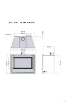
Page 32: ...32 TECHNICAL DRAWING 14...

Page 33: ...ENGINEER COMPANY NAME COMPANY ADDRESS POSTCODE 3RD YEAR SERVICE completion date SERVICE ENGINEER COMPANY NAME COMPANY ADDRESS POSTCODE 4TH YEAR SERVICE completion date SERVICE ENGINEER COMPANY NAME C...

Page 34: ...s __________ Overall length of flue __________ Is there any spillage __________Is the draught excessive __________ Is there any permanent ventilation in the room __________ Has the room double glazing...

Page 35: ...out by the purchaser or any third party not authorised by us or the appliance has been misused or accidentally damaged or damage is due to fair wear and tear or the appliance or defective component s...

Page 36: ...36 Ink 00 7066 Wanders METAALPRODUCTEN B V AMTWEG 4 7077 AL Netterden NL Tel 31 0 315 386414 Fax 31 0 315 386201 e mail info wanders nl www wanders com...

Reviews: