Rev. 1.1
Assembly Instructions - Hand-Spray Valve SMS-15
Page 12 of 18
Walther Systemtechnik GmbH
– D 76726 Germersheim
Telefon: +49 (0)7274-7022-0 Telefax: +49 (0)7274-7022-91
http://www.walther-2000.de
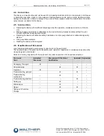
8.3 Maintenance for Operation in Color Marking Systems (normal operation)
The spray cap will be cleaned every other day with a special thinner and a soft cloth. Make sure that no cloth
fibers are left on the nozzle tip.
The material section of the spray valve should be cleaned with a special thinner every other week. Please
observe the following steps:
Completely open needle lock (remember raster setting for later use!)
Remove air cap and unscrew nozzle with a SW 6 open wrench
IMPORTANT
Hold spray valve downwards so that no medium can flow into the air channels. Dis-
charged medium will be collected in a container and disposed of later.
Clean with a soft (paint-)brush and a special thinner.
Re-assemble nozzle and air cap after cleaning.
Re-set the raster-needle setting
A cleaning cycle will be initiated after standstills (e.g. breaks over night or on weekends). The nozzle will be
sprayed clean. This cleaning cycle will be activated through the system controls.
IMPORTANT
Use a dummy or a cloth during the cleaning cycle in order to avoid soiling!
After longer system standstills (e.g. 2-3 weeks), the complete system will be cleaned before re-start. If nec-
essary, the material hoses and if applicable, also the inlays of the pressure tank have to be replaced.
The material pressure container will be opened every week and the color will be thoroughly stirred (if no agi-
tator is provided).
The material pressure container will be cleaned every 3-4 months; material lines and inlays will be
exchanged.
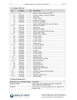
8.4 Replacing Needle (Pos. 1.6), Air Valve (Pos. 4.0) and Nozzle (Pos. 1.1)
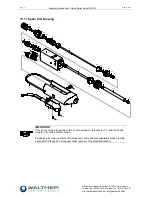
Completely unscrew raster-needle lock (Pos.6.0). Unscrew nozzle extension (Pos.2.1 resp. 2.2) with retainer
ring (Pos.2.1). Unscrew nozzle (Pos.1.1). Carefully push needle (Pos.7.0) with air valve (Pos.4.0) from the
nozzle side to the back and carefully extract with a pair of tongs. Install new parts which are slightly greased
in reverse order. We do not recommend reusing previously employed needles. Leakages can be caused if O-
rings (Pos.3.1) are pinched by needles which are not completely clean.
8.5 Replacing the Sealing Screw (Pos. 3.0)
Unscrew raster-needle lock completely (Pos.6.0). Remove nozzle extension (Pos.2.1 resp. 2.2) with retainer
ring (Pos. 2.1). Unscrew nozzle (Pos.1.0). Carefully push needle (Pos.7.0) with the air valve (Pos.4.0) from
the nozzle side to the back and carefully extract with a pair of tongs. Then use a screwdriver SW11 to un-
screw the sealing screw (Pos.3.0) from the thread.


