6
BA201
Step 5
•
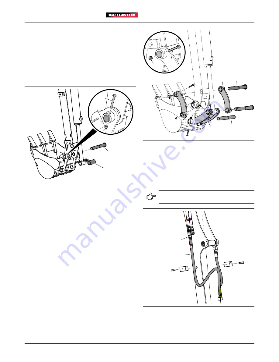
Install the bucket (purchased separately). Align the bucket
main pivot to the dipper main pivot.
•
Position the
6089W250
chain hook (7) with the dipper
main pivot.
•
Insert
3011W1170
flanged pin (6) through dipper, chain
hook, and pivot.
•
Secure with
Z71120
1/4"NC x 2" Hex bolt (11) and
Z72211
Hex Locknut (12).
6
11
12
7
Fig. 6 –
Install Bucket
Step 6
•
Install bucket tilt linkage. Fit the bucket link into the
secondary bucket pivot.
•
Insert a
3011W109
1.0" x 7.45" Flanged Pin (2) through
secondary pivot and
3011W103
Middle Linkage (5).
Secure with
Z71120
1/4"NC x 2" Hex bolt (11) and
Z72211
Hex Locknut (12).
•
Fit the
3011W102
Linkage Arms (4) to the secondary
dipper pivot, then insert
3011W170
1.0" x 7.45" Flanged
Pin (6) through secondary dipper pivot and link arms.
Secure with
Z71120
1/4"NC x 2" Hex bolt (11) and
Z72211
Hex Locknut (12).
•
Align the cylinder rod end bushing, the two linkage arms,
and the bucket linkage. Insert a
3011W170
1.0" x 7.45"
Flanged Pin (6), and secure with
Z71120
1/4"NC x 2" Hex
bolt (11) and
Z72211
Hex Locknut (12).
4
12
11
2
5
6
Fig. 7 –
Installing Tilt Linkage
Step 7
•
Connect the hydraulic hoses. Each hose is color-coded
to match the quick disconnects on the dipper boom, e.g.,
red to red, white/red to white/red. Connect each hose to its
appropriate color tag.
Hoses with blue tags are not used on the
backhoe installation.
10
9
Fig. 8 –
Quick-disconnect Hoses
•
Reinstall the hose clamps on the side of the dipper boom.
Summary of Contents for BA201
Page 15: ...WallensteinEquipment com...


