Service and Maintenance
BXTR5224
Wood Chipper
54
6.14 Upper Feed Roller Tension
Adjustment
The feed rollers pull material from the hopper into the chipper.
The lower roller is fixed. The upper roller is mounted on hinged
pivot arms so it can move up and down with different sizes of
material. Spring tension on the upper pivot arms hold the roller
down on the material as it is fed into the chipper.
Adjust spring tension tighter for smaller material, and looser for
larger material.
If spring tension needs to be adjusted, follow these steps:
Procedure
1.
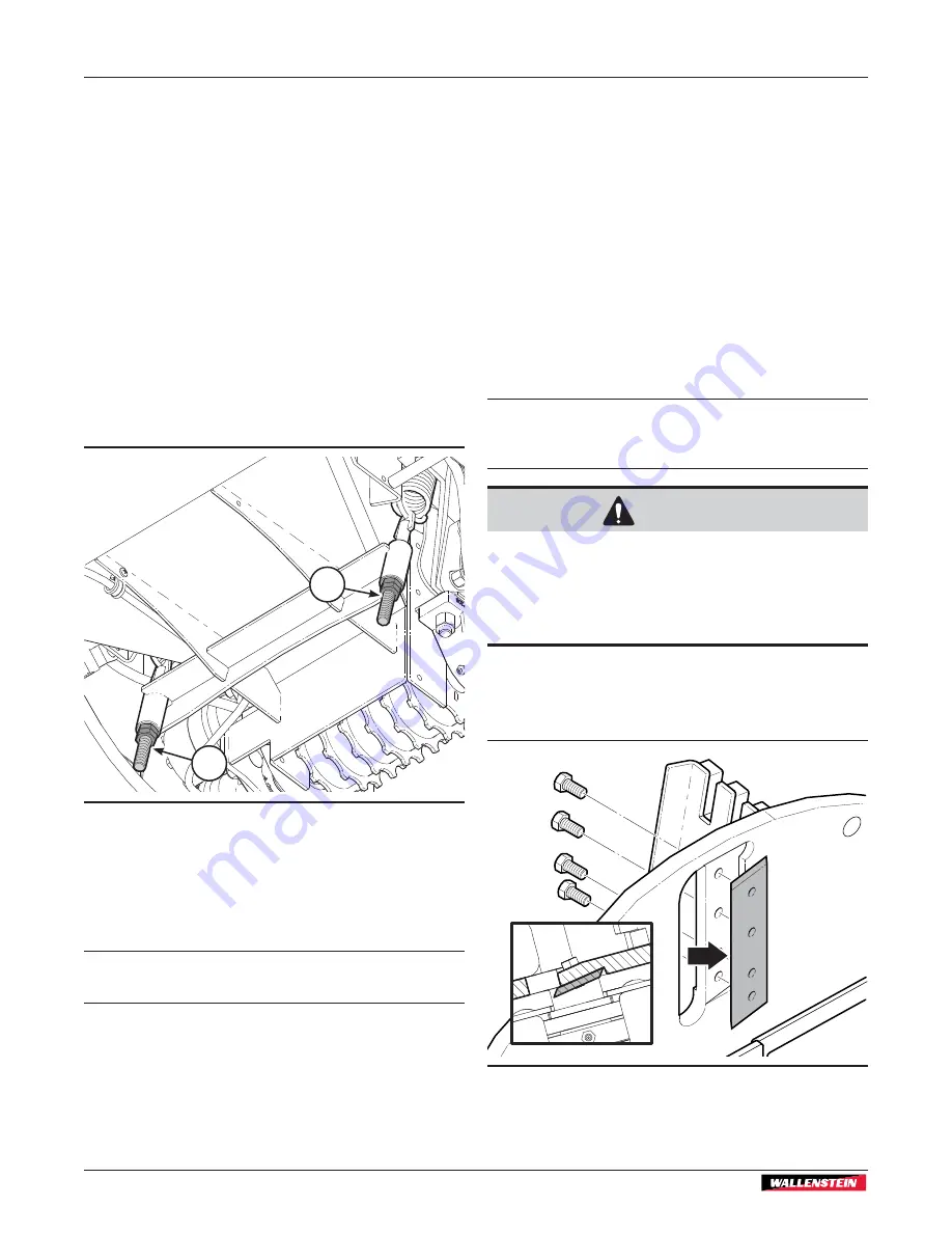
On the underside of the machine, loosen the jam nuts (1)
on the spring tensioners. Hold the upper nut with a wrench
while loosening the jam nut.
00150
Fig. 65 –
Upper feed roller tensioner (US model shown)
1
1
2.
Turn the adjuster nut to set spring tension as required. The
upper roller should grip material and move up and down
with different material sizes.
3.
Hold the adjuster nut with a wrench and tighten the jam nut.
IMPORTANT! Set tension on both sides equally. Measure
the length of adjustment threads as a check.
6.15 Rotor Blades – Changing
Check rotor blade sharpness daily.
Check blade sharpness more often if processing material with
a lot of sand, soil or dirt in it. If the chipper is not pulling the
material or material has to pushed into the chipper, the rotor
blades are probably dull.
Keeping the blades sharp reduces the amount of power required
during operation. Reverse or sharpen the blades if the cutting
edge becomes dull.
Procedure
1.
Remove the blades from the rotor to sharpen. Sharpen at a
45° angle to provide the best cutting effect.
IMPORTANT! Make sure equal amount of material is
removed from each blade when sharpening to maintain
proper rotor balance.
CAUTION!
Wear heavy gloves, turn the rotor slowly, and be
aware of your hand positions. The rotor knives
are sharp and can cause cuts. Finger and hands
can become pinched or wedged between the
rotor and the rotor housing.
W032
2.
Install rotor blades with leading edge out, towards the
ledger blade. Tighten the blade mounting bolts to
45 lbf•ft
(63 N•m)
.
00152
Fig. 66 –
Rotor blade leading edge


