background image

 English   

- 8 -

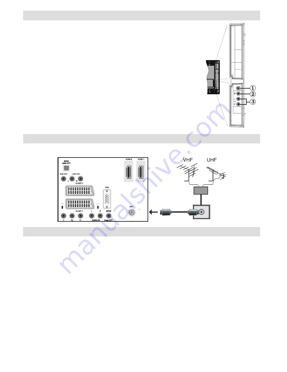
Viewing the Connections - Side Connectors

Headphone jack is used for connecting an external headphone to the 

1. 

system. Connect to the HEADPHONE jack to listen to the TV from 

headphones (optional).
Video Input is used for connecting video signals of external devices.Connect 

2. 

the video cable between the VIDEO IN socket on the TV and the VIDEO 

OUT jack on your device.

Audio Inputs are used for connecting audio signals of external devices. 

3. 

Connect the audio cable between the AUDIO INPUTS on the TV and the 

AUDIO OUTPUT jacks on your device. Note: If you connect a device to the 

TV via the VIDEO INPUT, you should also connect your device with an audio 

cable to the AUDIO INPUTS of the TV to enable audio.


Aerial Connection

• Connect the aerial or cable TV plug to the AERIAL INPUT socket located at the rear of the TV.


Power Connection

IMPORTANT

: The TV set is designed to operate on 220-240V AC, 50 Hz.

• After unpacking, allow the TV set to reach the ambient room temperature before you connect the set to the 

mains.

• Plug the power cable to the mains socket outlet.

Summary of Contents for WP4084FHD

Page 1: ...COLOUR TELEVISION WITH REMOTE CONTROL OPERATING INSTRUCTIONS WP4084FHD...

Page 2: ...ectors 9 Connecting Other Equipment via Scart 10 Inserting Batteries in the Remote Control Handset 10 Switching the TV On Off 10 To Switch the TV On 10 To Switch the TV Off 10 First Time Installation...

Page 3: ...tes the TV switches itself automatically to standby mode PLL Frequency Search PC input Plug Play for Windows 98 ME 2000 XP Vista Audio line out Game Mode optional Accessories EXIT GUIDE WIDE ABC DEF G...

Page 4: ...e heat such as an electric heater Ensure that no open flame sources such as lighted candles are placed on top of the TV Batteries should not be exposed to excessive heat such as sunshine fire or the l...

Page 5: ...ble LCD Screen The LCD panel is a very high technology product with about a million thin film transistors giving you fine picture details Occasionally a few non active pixels may appear on the screen...

Page 6: ...up 5 Cursor right 6 Cursor down 7 TV mode No function 8 Mono Stereo Dual I II 9 Programme up down 10 Numeric buttons 11 No function 12 Hold in TXT mode PIP position 13 Update in TXT mode PAP mode 14...

Page 7: ...ble to transfer audio signals to a device that has S PDIF input Subwoofer Out 2 is for connecting an external active subwoofer to the set to give a much deeper bass effect Use an appropriate RCA cable...

Page 8: ...r a device that connects to the TV via YPbPr Connect the PC audio cable between the AUDIO INPUTS on the TV and audio output of your PC to enable PC audio Connect the audio cable between AUDIO INPUTS o...

Page 9: ...ernal devices 3 Connect the audio cable between the AUDIO INPUTS on the TV and the AUDIO OUTPUT jacks on your device Note If you connect a device to the TV via the VIDEO INPUT you should also connect...

Page 10: ...to YPbPr source See Input selection section You may also connect through the SCART 1 or SCART 2 Use a SCART cable as shown below Note These three methods of connection perform the same function but i...

Page 11: ...e P CH or P CH button on the TV The TV will then switch on Note If you switch on your TV via PROGRAMME UP DOWN buttons on the remote control or on the TV set the programme that you were watching last...

Page 12: ...displayed on the screen Programme Selection Previous or Next Programme Press P button to select the previous programme Press P button to select the next programme Programme Selection Direct Access Pre...

Page 13: ...settings Store Press or button to select Store Press or OK button to store the settings Stored will be displayed on the screen Sound Menu Volume Press or button to select Volume Press or button to ch...

Page 14: ...nu highlight PIP item by pressing or buttons Press button to enter PIP submenu Using or button you can switch to PIP PAP mode or turn off the feature If the TV is switched to PIP or PAP mode Pip Pap s...

Page 15: ...ing controls the backlight level Select Backlight by pressing or button Press or button to set Backlight to Auto Medium Maximum or Minimum Menu Timeout To set a specific display timeout for menu scree...

Page 16: ...or button to select Store Program Press or OK button to store the settings Stored will be displayed on the screen Program Table Select Program Table by pressing or button By moving the cursor in four...

Page 17: ...ntrol and select PC input You can also use Source menu to switch to PC mode Note that PC mode menu settings are available only while the TV is in PC source PC Position Menu Select the first icon by pr...

Page 18: ...is indicated by a red frame around it The active window can be changed by pressing or button The status info OSD belongs to active window The place of the status OSDs are same for both windows Press t...

Page 19: ...may be aborted Teletext function buttons are listed below Teletext On Off PAT Mode Activates teletext mode when pressed once Pressing this button again will split the screen into two windows one displ...

Page 20: ...Sometimes you can improve the picture quality by changing the direction of the aerial Is the picture or teletext unrecognisable Check if you have entered the correct frequency Please retune the chann...

Page 21: ...VESA 25 1152 864 85 77 1 VESA 26 1152 870 75 68 9 MAC 27 1280 768 60 47 7 VESA 28 1360 768 60 47 7 29 1280 768 75 60 2 VESA 30 1280 960 60 60 0 VESA 31 1280 960 75 75 0 VESA 32 1280 960 85 85 9 VESA...

Page 22: ...r PC VGA TV RGB Scart1 RGB RGB RGB Scart2 RGB FAV RGB HDMI1 HDMI2 YPbPr PC VGA RGB This indicates that selection is possible only if Scart 1 has a RGB signal Restrictions Scart 1 source must have RGB...

Page 23: ...16 9 display 40 Screen Size DIMENSIONS mm DxLxH With foot 246 x 970 x 653 Weight Kg 15 1 DxLxH Without foot 99 x 970 x 613 Weight Kg 14 4 Products Battery Information for Users on Disposal of Old Equ...

Page 24: ...green or green and yellow The wire which is coloured blue or black must be connected to the terminal which is marked with the letter N or coloured Black The wire which is coloured brown or red must b...

Page 25: ...50155716...

Reviews: