Assembly Instructions
B23
22
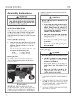
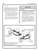
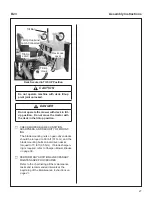
Hitch Pins Lock Deck
on Support Arms
Use Hitch Pins to Lock Deck on Support Arms
WARNING
Failure to install the hitch pins will result in
the deck disconnecting from the tractor
during operation.
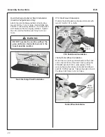
8. To reduce the weight of lifting the deck before
the counterweight spring is installed, remove
one
(1)
deck height hitch pin from a rear deck
support pin or alternately lift and block one
side of the deck. Decks with a deck height
adjuster installed will need to use the lift and
block technique.
Deck Height Hitch Pin
Remove One Deck Height Hitch Pin
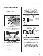
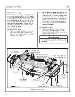
9. Re-engage the deck lock lever on the side
with the deck height hitch pin removed then
re-engage the second deck lock lever. Rein-
stall the deck height hitch pin or remove the
block.
CAUTION
Do not operate the machine with the deck
tilt-up pivot joint unlocked.
Deck Lock Lever
Engaged
Deck Lock Levers Engaged
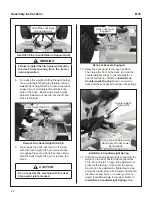
10. Raise the seat panel to the open position.
Then raise the front of the deck, and clip the
counterweight springs to the receptacle on
front of seat panel. (Refer to
Install Deck
Counterweight Spring
photo.) Lower the
deck and the seat panel to tension the springs.
Counterweight
Spring Clip
Spring Tension Adjustment
Nut Located Under Lower
Spring Hook
Install Deck Counterweight Spring
11. With the counterweight springs connected, the
weight on the deck caster wheels should be
15 to 25 Ib (6.8 to 11.3 kg); this adjustment is
preset at the factory. If required, the spring
tension can be adjusted by tightening or loos-
ening the elastic stop nuts located underneath
the lower spring hook, or contact your local
dealer if additional help is required. Refer to
Install Deck Counterweight Spring
photo.

