


15
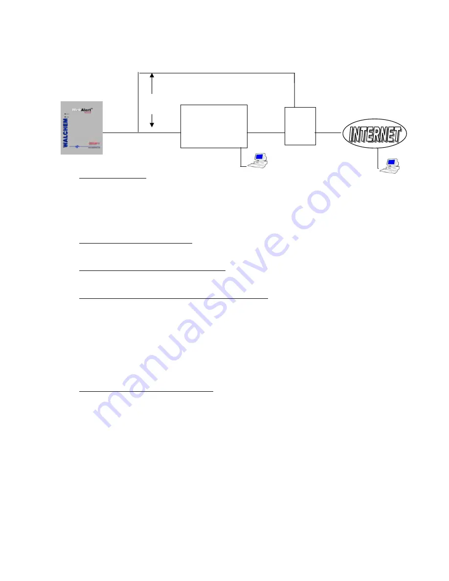
4.3.3 Ethernet Connection to LAN
Equipment Required
An Internet-ready computer with the following capabilities: 100 MHz minimum processor speed,
40 MB minimum RAM, Windows operating system, and Windows Internet Explorer version 5.0 or
higher web browser software.
A connection between the PC and the local area network (LAN).
An Ethernet connection between the WebAlert and the LAN.
Features Required in the WebAlert
All WebAlert process monitors are capable of Ethernet communications.
Utilities you need to set up on your computer
There are no special drivers, adapters or other software components required on the PC.
Parameters that need to be programmed into the WebAlert
Prior to attempting an Ethernet connection, the following information needs to be entered into the
Communication page of the WebAlert, either via a direct serial connection or via the Direct Modem
option. This information must be provided by the IT Administrator of the LAN.
The Ethernet IP address of the WebAlert. If the unit will only be accessed by computers on the
LAN then this may be a fake IP address. If the unit needs to be accessible by computers not on the
LAN then this must be a real IP address.
The Subnet Mask.
The Gateway IP address.
Steps Required to Establish a Connection
Open Internet Explorer.
Type in the Ethernet IP address that has been assigned by the IT Administrator.
The sign-on screen of the WebAlert will come up. Type the User Name and Password (Access
Code) in the text boxes and click the Submit button. The default user name is "webalert" and the
default passwords are "2001" for full access, "2002" for calibration only, and "2003" for read only.
These defaults can and should be changed in the Access Code page.
Web
Browser
LAN
Ethernet
ROUTER
Safe
Port
Unsafe
Port
OR
Web Browser
Summary of Contents for WebAlert WA500
Page 9: ...6 Figure 1 Identification of Parts...
Page 10: ...7 Figure 2 Wiring Diagram for AC Power Input...
Page 11: ...8 Figure 3 Wiring Diagram for Digital Inputs and Outputs...
Page 12: ...9 Figure 4 Wiring Diagram for Analog Inputs DEVICES POWERED BY THE WEBALERT...
Page 13: ...10 Figure 5 Wiring Diagram for USB Devices and Communications...
Page 14: ...11 4 0 FUNCTION OVERVIEW 4 1 Front Panel Alarm LED Status LED...


