background image

26 

Mounting 

EPSITRON® 


787-1675 Switched-Mode Power Supply with Integrated UPS Charger and Controller 


Manual 


Version 1.0.0  


Pos: 44 /All e Seri en ( Allgemei ne Module)/Ü berschriften für alle Serien/Monti eren - D emonti eren/M ontier en - Überschrift 1 @ 3\mod_1225446744750_21.doc @ 24900  @  1 @ 1 


Mounting 

Pos: 45 /Serie 787 (EPSITRON)/M ontier en/Montage 787- xxxx @ 11\mod_1317296048899_21.doc @ 80170 @ 22 @ 1 


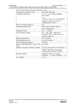
The 

EPSITRON

®

 device is designed for mounting on a DIN 35 rail. 

4.1 

Mounting the 

EPSITRON

®

 Device on the DIN 35 Rail 


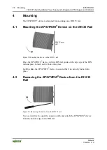
Figure 9: Mounting the device on the DIN 35 rail. 

Place the 

EPSITRON

®

 device with its DIN rail guide on the top edge of the DIN 

rail and press it down until it locks into place. 

Lightly shake the 

EPSITRON

®

 device to ensure that it is correctly locked into 

place. 

4.2 

Removing the 

EPSITRON

®

 Device from the DIN 35 

Rail 


Figure 10: Removing the device from the DIN 35 rail. 

Use a screwdriver to open the snap-on catch and detach the 

EPSITRON

®

 device 

from the bottom edge of the DIN rail. 

Pos: 46 /D okumentation allgemei n/Glieder ungselemente/---Seitenwechsel--- @ 3\mod_1221108045078_0.doc @  21810 @  @ 1 


Summary of Contents for EPSITRON 787-1675

Page 1: ...6_0 doc 64941 1 Manual EPSITRON Switched Mode Power Supply with Integrated UPS Charger and Controller 787 1675 Version 1 0 0 Pos 3 Alle Serien Allgemeine M odule Hinweise zur Dokumentati on Impressum für Standardhandbücher allg Ang aben Anschriften Tel efonnummer n und E Mail Adressen 3 mod_1219151118203_21 doc 21060 1 ...

Page 2: ...8 87 5 55 Fax 49 0 571 8 87 85 55 E Mail support wago com Every conceivable measure has been taken to ensure the accuracy and completeness of this documentation However as errors can never be fully excluded we always appreciate any information or suggestions for improving the documentation E Mail documentation wago com We wish to point out that the software and hardware terms as well as the tradem...

Page 3: ...Battery Control and Signaling Contacts 16 3 2 4 RS 232 Interface 16 3 3 Display Elements 17 3 4 Operating Elements 18 3 4 1 Rotary Switch for Output Voltage 18 3 4 2 Rotary Switch for Timed Buffer Mode 18 3 5 Technical Data 19 3 5 1 Device Data 19 3 5 2 Technical Data Input 19 3 5 3 Technical Data Output 20 3 5 3 1 Technical Data for the Output during Operation with Mains System20 3 5 3 2 Technica...

Page 4: ...attery Testing 31 6 5 1 Charging 31 6 5 2 Presence Test 31 6 5 3 Quality Test 32 6 5 4 Replacement 32 6 6 Battery Mode 32 6 6 1 Switch On Threshold for Battery Mode 33 6 6 2 Timed Battery Mode 33 6 6 3 Battery Mode in the IPC Mode PC Mode 33 6 6 3 1 Delay Time 34 6 6 3 2 Shut Down PC 35 6 6 3 3 PC Idle Off Time 35 6 6 4 Deactivating the Battery Mode 36 6 6 5 Deep Discharge Protection during Batter...

Page 5: ...if applicable Pos 9 Seri e 787 EPSITR ON Hinweise zur Dokumentation Gültig keit D okumentation U nterbr echungsfrei e Str omversorgung 787 1675 13 mod_1346059075423_21 doc 101963 1 This documentation applies to the switched mode power supply with integrated ups charger and controller 787 1675 Pos 10 1 All e Serien Allgemei ne Module Hi nweise zur D okumentati on Urheberschutz ausführlich 4 mod_123...

Page 6: ...Pos 10 4 4 All e Serien Allgemei ne Module Wichtige Erläuterungen Sicherheits und sonstig e Hinweise Vorsicht Vorsicht _War nung vor Personenschäden allgemei n_ Erl äuter ung 13 mod_1343310028762_21 doc 101038 1 Personal Injury Indicates a low risk potentially hazardous situation which if not avoided may result in minor or moderate injury Pos 10 4 5 All e Serien Allgemei ne Module Wichtige Erläute...

Page 7: ...ntegrated UPS Charger and Controller Manual Version 1 0 0 Additional Information Refers to additional information which is not an integral part of this documentation e g the Internet Pos 10 5 Dokumentation allgemei n Glieder ungselemente Seitenwechsel 3 mod_1221108045078_0 doc 21810 1 ...

Page 8: ... Font Conventions Table 2 Font conventions Font type Indicates italic Names of paths and data files are marked in italic type e g C Programme WAGO I O CHECK Menu Menu items are marked in bold letters e g Save A greater than sign between two names means the selection of a menu item from a menu e g File New Input Designation of input or optional fields are marked in bold letters e g Start of measure...

Page 9: ...oducts are always mentioned without any reference to patent rights Thus the existence of such rights cannot be excluded Pos 13 4 Serie 787 EPSITRON Wichtige Erläuterungen Personalqualifi kation 787 xxxx 11 mod_1317113061338_21 doc 79692 3 1 2 1 2 Personnel Qualifications All sequences implemented on 787 Series devices may only be carried out by electrical specialists with sufficient knowledge in a...

Page 10: ...es The components to be supplied Ex Works are equipped with hardware and software configurations which meet the individual application requirements WAGO Kontakttechnik GmbH Co KG will be exempted from any liability in case of changes in hardware or software as well as to non compliant usage of components Please send your request for modified and new hardware or software configurations directly to ...

Page 11: ...n auch bei Ausfall der Netzspannung 14 mod_1363599131481_21 doc 114650 1 Voltage present at the load terminals even on loss of power supply Voltage continues to be present at the load terminals even when there is a loss of power supply and the device switches to the buffer mode Therefore never touch the load terminals In this case always remove the jumper between R0 and R1 to de energize the load ...

Page 12: ...erien Allgemeine M odul e Wichtige Erläuter ung en Sicherheits und sonstige Hinweise Achtung Achtung Kein Kontaktspray ver wenden 6 mod_1260181290808_21 doc 46755 1 Do not use any contact spray Do not use any contact spray The spray may impair contact area functionality in connection with contamination Pos 13 21 Alle Serien Allgemeine M odul e Wichtige Erläuter ung en Sicherheits und sonstige Hinw...

Page 13: ...a 24V DC battery module for buffering not included in the scope of supply Pos 16 3 Serie 787 EPSITRON Ger ätebeschrei bung Beschr eibung Funkti on Funkti on 787 1675 Wirkungsweise der Komponenten 13 mod_1342600188912_21 doc 100544 1 All of the components that can be used to set up an uninterruptible power supply system are optimally matched to and compatible with one another These components can b...

Page 14: ...ice description Connections Load 2 Rotary switch for setting the output voltage Device Description Operating Elements Rotary Switch for Output Voltage 3 CAGE CLAMP connections for 100 240 VAC input voltage Device Description Connections Power Supply 4 RS 232 serial interface Device Description Connections RS 232 Interface 5 LEDs Device Description Display Elements 6 Rotary switch for setting the t...

Page 15: ... 3 2 1 Supply Table 4 Power supply connections Figure 2 Supply connection No Designatio n Function 1 L Input voltage 100 240 VAC 2 N N conductor 3 PE Ground conductor Pos 22 2 Serie 787 EPSITRON Ger ätebeschrei bung Anschl üsse Anschl üsse 787 1675 Last 13 mod_1347884939616_21 doc 102884 3 1 3 2 2 Load Table 5 Terminals Load Figure 3 Load terminals No Designatio n Function 1 Output voltage 24 VDC ...

Page 16: ...e shutdown in Buffer mode 7 34 Signal output Bat Charge 8 24 Signal output Bat Mode 9 14 Signal output Alarm 10 13 External supply voltage 24 VDC for signal outputs 7 8 and 9 Pos 22 4 Serie 787 EPSITRON Ger ätebeschrei bung Anschl üsse Anschl üsse 787 1675 RS 232 Schnittstelle 13 mod_1347962772871_21 doc 102970 3 1 3 2 4 RS 232 Interface Table 7 Connections RS 232 interface Figure 5 RS 232 interfa...

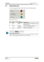
Page 17: ...Display elements Table 8 Legend for Indicators figure No LED Designation Explanation 1 red Alarm The unit is faulted or the Battery mode is being terminated 2 yellow Charge Bat Mode The unit is charging the batteries or is operating in the Battery mode 3 green DC OK The unit is ready for use Further signaling possible Other statuses can also be indicated if an error occurs For information about th...

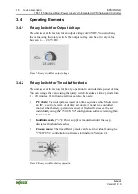
Page 18: ...otary Switch for Timed Buffer Mode The unit is set at the factory for battery operation for an indefinite period of time You can change this value using the rotary switch Besides set time periods from 1 20 minutes the following settings can also be made PC Mode The unit operates based on a time sequence which shuts down an IPC a control system or display and operator panel in a controlled manner w...

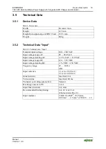
Page 19: ...mm 2 36 in Height 127 mm Height from upper edge of DIN 35 rail 135 5 mm Weight 800 g 3 5 2 Technical Data Input Table 10 Technical data Input Nominal input voltage 100 240 VAC Input voltage range AC 85 264 VAC Input voltage derating AC 1 5 VAC 110 VAC Input voltage range DC 120 372 VDC Input voltage derating DC 1 VDC 150 VDC Frequency range 47 63 Hz 0 Hz Input current Ie 1 1 A for 230 VAC 2 2 A fo...

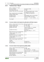
Page 20: ...on with the mains system Nominal output voltage 24 VDC SELV Output voltage range 23 28 5 VDC Output current limit starting at approx 1 1 x nominal current constant current Adjustment accuracy less than 1 Static load change 10 90 Maximum power loss at nominal load 100VAC input voltage and fully charged battery 22 W Maximum power loss at nominal load 230VAC input voltage and fully charged battery 17...

Page 21: ...ge protection yes Charging characteristics Three stage charging process IUoU characteristic Charging current 0 3 0 6 ADC End of charge voltage 26 29 5 VDC temperature controlled These values can be set using the software Battery presence test 1 x per minute Remaining power test every 10 minutes Deep discharge protection 19 VDC Message threshold Battery power very low 20 4 VDC Parallel connection o...

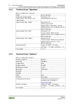
Page 22: ...losed Battery mode Signal options can be configured via the RS 232 interface Signal output Bat Charge Maximum 30 V Contact closed Battery being charged Signal options can be set via the RS 232 interface Signal terminals CAGE CLAMP 721 Series 0 08 mm2 2 5 mm2 AWG 28 12 Line length 3 m 3 5 5 Technical Data Interface Table 15 Technical Data Interface Interface standard RS 232 Data lines TxD RxD Contr...

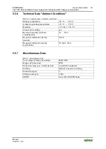
Page 23: ...g yes Relative humidity without condensation 30 85 Requisite minimum spacing lateral 0 mm Requisite minimum spacing top bottom 50 mm 1 96 in 3 5 7 Miscellaneous Data Table 17 Miscellaneous data Test voltage Primary Secondary 4200 VDC Degree of protection IP20 Protection class acc to EM 61140 I with PE conductor Cooling Natural convection cooling Pollution degree 2 Climatic category 3 K3 MTBF more ...

Page 24: ...N Ger ätebeschrei bung Zulassungen Zulassungen U nterbr echungsfrei e Stromversorgung 787 xxxx allgemein ohne Variantenangabe Ei nlei tun 13 mod_1347518988157_21 doc 102690 1 The following approvals have been awarded to the uninterruptible power supply system 787 1675 Pos 34 All e Seri en Allgemei ne Module Zulassungen Standardzulassungen C E Konformitätskennzeichnung 3 mod_1224494777421_21 doc 24...

Page 25: ...EMC Pos 39 All e Seri en Allgemei ne Module N or men und Richtli nien Sicherheit DIN EN 61558 2 16 2009 13 mod_1346665322780_21 doc 102246 1 Safety of transformers reactors IEC 61558 2 16 2009 power supply units and similar products for supply voltages up to 1100 V Part 2 16 Particular requirements and tests for switch mode power supply units and transformers for switch mode power supply units Pos...

Page 26: ...IN 35 rail 4 1 Mounting the EPSITRON Device on the DIN 35 Rail Figure 9 Mounting the device on the DIN 35 rail Place the EPSITRON device with its DIN rail guide on the top edge of the DIN rail and press it down until it locks into place Lightly shake the EPSITRON device to ensure that it is correctly locked into place 4 2 Removing the EPSITRON Device from the DIN 35 Rail Figure 10 Removing the dev...

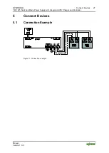
Page 27: ...4172889468_21 doc 27460 1 1 5 Connect Devices Pos 48 All e Seri en Allgemei ne Module Ü berschriften für alle Serien Anschließen Anschl ussbeispiel Überschrift 2 4 mod_1242621672468_21 doc 33293 2 1 5 1 Connection Example Pos 49 Serie 787 EPSITRON Anschli eßen Anschlussbeispi el 787 1675 13 mod_1346146843608_21 doc 102040 1 Figure 11 Connection example Pos 50 D okumentation allgemei n Glieder ungs...

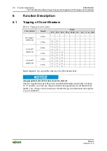
Page 28: ...ng of circuit breakers Cross Section Length Fuse W 2 W 3 W 4 W 6 W 10 C 2 C 4 C 6 C 10 0 75 mm2 AWG 18 40 m 20 m x x x x 1 5 mm2 AWG 16 40 m x x x x 20 m x x x x x x 2 5 mm2 AWG 14 40 m x x x x x x 20 m x x x x x x Rapid magnetic trip is possible only up to the B4 characteristic An appropriate circuit breaker must be selected The line lengths listed here have been established through experiments a...

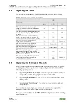
Page 29: ...ss than 20 4 V On blinks quickly Off The unit s deep discharge protection system has terminated the Battery mode battery voltage 19 2 V signaling will be continued for a maximum of 10 hours Off Off blinks slowly The unit is operating in the Battery mode and the DC output has been de activated on account of excessive current Off on off blinks blinks slowly Pos 55 Serie 787 EPSITRON Funkti onsbeschr...

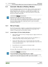
Page 30: ... this is given in the battery manufacturer s data sheet 6 4 1 Battery Charging The 787 87x Series battery modules are equipped with an internal temperature sensor of type NTC K164 4 7 kΩ which measures the temperature of the module It is installed directly in each battery module 6 4 1 1 Connecting the 787 Series Battery Modules 1 Ensure that the unit is not live by removing the power supply and th...

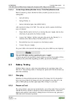
Page 31: ... The red LED lights up when applying the power supply A fault is present is the red LED remains lit after power has been applied If this happens refer to the table Signaling via LEDs given in this manual Pos 57 Serie 787 EPSITRON Funkti onsbeschrei bung Batteriepr üfungen 787 1675 13 mod_1343027870471_21 doc 100680 23333 1 6 5 Battery Testing Different battery tests are carried out depending on th...

Page 32: ...ntinued on a loss of power supply when intact fault free battery modules are used 6 5 4 Replacement If the battery service life has expired the batteries used in the module must be replaced either in pairs or the complete module must be replaced Consult the instruction manual for this that came with your battery module Pos 58 Serie 787 EPSITRON Funkti onsbeschrei bung Batteriebetrieb 787 1675 13 m...

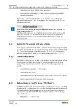
Page 33: ...below the set switch on threshold The factory default setting for the switch on threshold is 22 V You can also set this threshold using the 759 870 V2 configuration software starting from Version 2 5 to custom values between 20 25 5 V 6 6 2 Timed Battery Mode The unit is set at the factory for battery operation for an indefinite period of time At this setting the entire battery capacity is set to ...

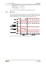
Page 34: ...he time sequence for the individual actions is permanently defined 6 6 3 1 Delay Time The unit s output is not de activated if power is restored within the set delay time The signal output Bat Mode remains inactive so that no signal is generated that would shut down the IPC This is illustrated in the following flow chart Figure 12 Flow chart Input voltage restored during the set delay time ...

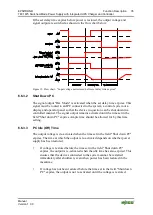
Page 35: ...controlled manner The signal output remains activated until the time set in the field Shut down PC expires Ample time should be allowed for by this time setting 6 6 3 3 PC Idle Off Time The output voltage is de activated when the time set in the field Shut down PC expires The time at which the output is re activated depends on whether power supply has been restored If voltage is restored before th...

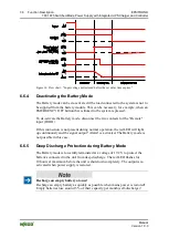
Page 36: ...ntacts for the Remote input R0 R1 If this connection is not present during normal operation the red LED will light up continuously and the signal output Alarm is activated The Battery mode is not possible in this case 6 6 5 Deep Discharge Protection during Battery Mode The Battery mode is forcefully terminated at a voltage of 19 2 V to protect the batteries connected to the unit from deep discharg...

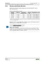
Page 37: ... A 25 A slow 1 5 mm2 AWG 16 787 872 7 0 Ah 40 A 25 A slow 2 5 mm2 AWG 14 787 873 12 Ah 40 A 25 A slow 2 5 mm2 AWG 14 Please note that the permanent output current at the unit is limited For more detailed information refer to the technical data Regardless of the recommended battery modules any type of lead gel or lead acid absorbed glass mat AGM battery can be used Observe the data sheet Always obs...

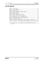
Page 38: ... 5 RS 232 interface 16 Figure 6 Display elements 17 Figure 7 Rotary switch for output voltage 18 Figure 8 Rotary switch for battery operation 18 Figure 9 Mounting the device on the DIN 35 rail 26 Figure 10 Removing the device from the DIN 35 rail 26 Figure 11 Connection example 27 Figure 12 Flow chart Input voltage restored during the set delay time 34 Figure 13 Flow chart Input voltage not restor...

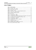
Page 39: ...ignaling contacts 16 Table 7 Connections RS 232 interface 16 Table 8 Legend for Indicators figure 17 Table 9 Device data 19 Table 10 Technical data Input 19 Table 11 Technical data Output 20 Table 12 Technical data for the output during operation with the mains system 20 Table 13 Technical data for the output during Battery mode 20 Table 14 Technical data Signaling 22 Table 15 Technical Data Inter...

Page 40: ...eite 9 mod_1285229376516_21 doc 64944 1 WAGO Kontakttechnik GmbH Co KG Postfach 2880 D 32385 Minden Hansastraße 27 D 32423 Minden Phone 49 5 71 8 87 0 Fax 49 5 71 8 87 1 69 E Mail info wago com Internet http www wago com Ende der Liste für Textmar ke Ei nband_hinten ...

Reviews: