WAGO-I/O-SYSTEM 750
Fieldbus Communication
87
750-306 DeviceNet
TM
Fieldbus Coupler
Manual
Version 2.0.0
in devices with
1 MΩ (DIN rail contact). A low-impedance connection of the
shielding to PE is possible only from the outside (e.g., by a supply module). The
aim is a central PE contact for the entire DeviceNet
TM
bus cable shield.
Use the WAGO Shield Connecting System for optimal shielding!
For the optimal connection between fieldbus cable shielding and functional
ground, WAGO offers a cable shielding system (Series 790).
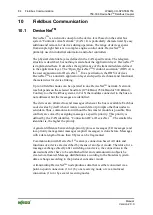
Each DeviceNet
TM
node forms the UDiff differential voltage from the CAN_High
and CAN_Low as follows: UDiff = UCAN_High - UCAN_Low.
The differential signal transmission offers the benefit of insensitivity to common
mode interferences and ground offsets between the nodes.
Use the proper terminating resistor for both ends of the bus cable!
The bus c
able must have a terminating resistor of 121 Ω / ±1% / ¼ W at both ends
between CAN-High and CAN-Low to prevent reflections and transmission
problems.
This is also required for very short cable lengths.
Because the CAN bus can be designed as a 2-wire bus, bus fault management
detects a break or short circuit in a line by asymmetric operation.
Additional Information
The “CAN in Automation” (CiA) organization makes specification documents for
a CAN network available on the Internet at:

