22
System Description
WAGO-I/O-SYSTEM 750
750-306 DeviceNet
TM
Fieldbus Coupler
Manual
Version 2.0.0
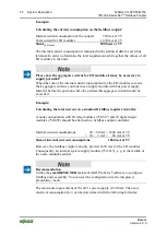
Example:
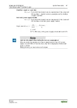
Calculating the current consumption on the fieldbus coupler:
Internal current consumption of the coupler
350 mA at 5 V
Total current for I/O modules
1650 mA at 5 V
Sum I
(5 V) total
2000 mA at 5 V
The internal current consumption is indicated in the technical data for each bus
terminal. In order to determine the total requirement, add together the values of all
I/O modules in the node.
Please note the aggregate current for I/O modules. It may be necessary to
supply potential!
When the sum of the internal current consumption for the I/O modules exceeds
their aggregate current, you must use a supply module with bus power supply.
Install it before the position where the permissible aggregate current would be
exceeded.
Example:
Calculating the total current on a standard fieldbus coupler/controller:
A node configuration with 20 relay modules (750-517) and 30 digital input
modules (750-405) should be attached to a fieldbus coupler/controller:
Internal current consumptions
20 × 90 mA = 1800 mA at 5 V
+ 30 × 2 mA = 60 mA at 5 V
Sum of internal current consumptions
1860 mA at 5 V
However, the fieldbus coupler can only provide 1650 mA for the I/O modules.
Consequently, an internal system supply module (750-613), e. g. in the middle of
the node, should be added.
Recommendation
Utilize the
smartDESIGNER
feature WAGO ProServe
®
software to configure
fieldbus node assembly. You can test the configuration via the integrated
plausibility check.
The maximum input current of the 24 V system supply is 500 mA. The exact
electrical consumption (I
(V)
) can be determined with the following formulas:

