Fieldbus Controller • 79
Fieldbus Controller 750-872/020-000
WAGO-I/O-SYSTEM 750
ETHERNET TCP/IP
Note
You will find the most current version of the data sheets in the internet under
www.wago.com.
10. Accept changes in the node configuration and close the dialog box by
pressing the '
OK
' button. The addresses in the PLC-configuration are
recalculated and the tree structure is refreshed afterwards.
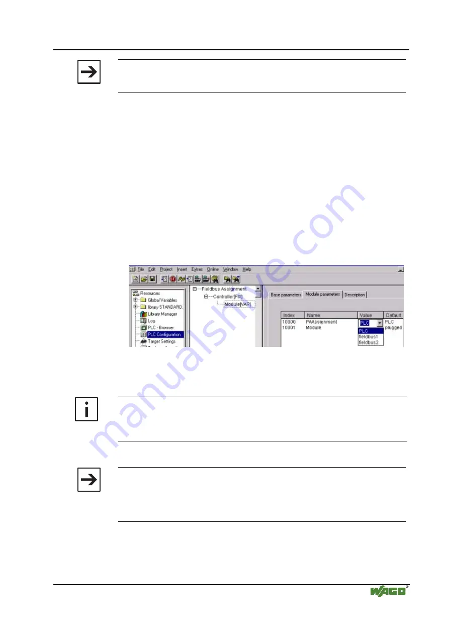
11. You can change now the access authorization, if for individual modules, the
write access should be via the fieldbus (MODBUS TCP/IP or Ethernet/IP).
For each module added, the write access first is fixed from the PLC.
You can change it by determining in the right-hand dialogue
window/register "
Module parameter
s for each individual module, from
where the write access on the I/O Module data should take place.
For this in the "
Value
" column. your options include:
- PLC (The PFC controls its I/O locally)
- fieldbus 1 (A MODBUS TCP Fieldbus Master controls the I/O module)
- fieldbus 2 (An Ethernet IP Fieldbus Master controls the I/O module)
12. When you have completed the assignments, you can start programming with
the IEC 61131-3 program tool. The configuration file “EA-config.xml” is
generated as soon as you compile the project.
More information
For a detailed description on how to use the software WAGO-I/O-PRO CAA
and the I/O-Configurator, please refer to the Online-Help of WAGO-I/O-
PRO
CAA.
Note
Alternatively, the "EA-config.xml" file can be created with each editor and
then be transported via FTP in the Controller directory "/etc".
The configuration with the “EA-config.xml” file, which is already stored in
the controller, is described in the following chapter.


