background image

52

Super Finish 33 PRO


GB

10 

REPAIRS AT THE UNIT

Switch the unit off.
Before all repair work: Unplug the power 
plug from the outlet.

10.1 

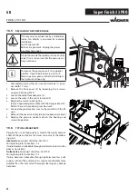
INLET VALVE PUSHER

1.  Use a 17 mm spanner to screw out the inlet valve button.
2.  Replace the wiper (1) and O-ring (2).

10.2 

INLET VALVE

1.  Place the enclosed 30 mm wrench on the trigger housing 

(1).

2.  Loosen the trigger housing (1) with light blows of a ham-

mer on the end of the wrench.

3.  Screw out the trigger housing with the inlet valve (2) from 

the paint section.

4.  Pull of the clasp (3) using the enclosed screwdriver.
5.  Place the enclosed 30 mm wrench on the inlet valve (2). 

Turn out the inlet valve carefully.

6.  Clean the valve seat (4) with a cleaning agent and brush 

(ensure that no brush hairs are left behind).

7.  Clean the seals (5, 6) and check for damage. Replace, if 

necessary.

8.  Check all the valve parts for damage. In case of visible 

wear replace the inlet valve.

REPAIRS AT THE UNIT

Installation

1.  Insert the inlet valve (2) into the trigger housing (1) and 

secure with the clasp (3). Ensure that the (black) seal (5) is 
mounted in the trigger housing.

2.  Screw the unit from the trigger housing and the inlet valve 

into the paint section. The same (black) seal (6) has to be 
mounted in the paint section.

3.  Tighten the trigger housing with the 30 mm wrench and 

tighten with three light blows of the hammer on the end 
of the wrench. (Corresponds to approx. 90 Nm tightening 
torque).

1

2

1

3

2

5

6

4

Summary of Contents for Super Finish 33 Pro

Page 1: ...SUPER FINISH 33 PRO ORIGINALBETRIEBSANLEITUNG wagner group com D GB F I D Betriebsanleitung 1 GB Operating manual 38 F Mode d emploi 73 I Istruzioni per l uso 109 ...

Page 2: ...ce with the operating manual before every start up 1 Faulty units may not be used 2 Secure a Wagner spray gun with the securing lever at the trigger guard 3 Ensure earthing 4 Check the permissible operating pressure of the high pressure hose and spray gun 5 Check all the connecting parts for leaks 3 Instructions for regular cleaning and maintenance of the unit are to be observed strictly Observe t...

Page 3: ...___________________ 46 4 2 unit with upper hopper ______________________ 46 4 3 High pressure hose and spray gun______________ 46 4 4 Connection to the mains network ______________ 46 4 5 Cleaning preserving agent when starting up of operation initially ___________________________ 47 4 6 Ventilate unit hydraulic system if the sound of inlet valve is not audible______________________ 47 4 7 Taking ...

Page 4: ...s etc in the vicinity 1 4 DANGER OF INJURY FROM THE SPRAY JET Attention danger of injury by injection Never point the spray gun at yourself other persons or animals Never use the spray gun without spray jet safety guard The spray jet must not come into contact with any part of the body In working with Airless spray guns the high spray pressures arising can cause very dan gerous injuries If contact...

Page 5: ...ting material These can cause sparks and flames upon discharge The unit must therefore always be earthed via the electrical system The unit must be connected to an appropriately grounded safety outlet An electrostatic charging of spray guns and the high pressure hose is discharged through the high pressure hose For this reason the electric resistance between the connections of the high pressure ho...

Page 6: ...he top container for paintwork 2 2 COATING MATERIAL Dilutable lacquers and paints or those containing solvents two component coating materials dispersions latex paints façade paints roof and attic coatings fire and corrosion pro tection material No other materials should be used for spraying without WAG NER s approval Pay attention to the Airless quality of the coating materials to be processed Th...

Page 7: ...n high pressure paint spraying equipment The electric motor drives the hydraulic pump via planetary gears 1 A piston 2 is moved up and down so that hydraulic oil is moved under the diaphragm 3 which then moves In detail The downwards movement of the machine opens the disk in let valve 4 automatically and coating material is sucked in During the upwards movement of the diaphragm the coating materia...

Page 8: ...cessary In this case please ensure that no attachments can be damaged Atten tion Paint or solvent residues can escape from the connec tions 1 3 3 EXPLANATORY DIAGRAM 1 Tip guard with airless tip 2 Spray gun 3 High pressure hose 4 Connection for high pressure hose 5 Pressure gauge 6 Pressure control valve 7 ON OFF switch 8 Pressure relief valve Symbols shown in the recess of the switch Spraying Cir...

Page 9: ... Hydraulic oil filling quantity 1 0 liter Divinol HVI 15 Max tyre pressure 0 2 MPa 2 bar Max vibration at the spraygun lower than 2 5 m s Max sound pressure level 76 dB A Place of measurement 1 m distance from unit and 1 60 m above floor 12 MPa 120 bar operating pressure reverberant floor 3 5 TOOL BOX The SF 33 comes with an integrated tool box As well as provi ding sufficient storage space for al...

Page 10: ...older with the selected tip onto the spray gun align tip and tighten union nut 4 2 UNIT WITH UPPER HOPPER 1 Ensure that the sealing surfaces of the connections are clean Ensure that the red inlet 1 is inserted in the coat ing material inlet 4 2 Screw the adapter 8 onto the coating material inlet 4 and tighten until hand tight 3 Place the hopper 9 on the adapter 8 4 Screw the union nut 5 on the ret...

Page 11: ...it with hopper 2 Fill coating material into the hopper 3 Press inlet valve pusher 4 several times to release pos sibly clogged inlet valve 4 Open the relief valve 2 valve setting circulation the unit will start 5 Turn the pressure regulating knob 1 to the right until the stop is reached When the noise of the valves changes the unit is bled and takes in coating material 6 If coating material exits ...

Page 12: ...gh pressure hose Protect against sharp objects and edges Never pull on the high pressure hose to move the device Make sure that the high pressure hose cannot twist This can be avoided by using a Wagner spray gun with a swivel joint and a hose system When using the high pressure hose while working on scaffolding it is best to always guide the hose along the outside of the scaf folding The risk of d...

Page 13: ...he pressure at the pres sure control valve slowly in order to obtain a higher mate rial flow 7 Open the relief valve valve setting circulation 8 Pump suitable cleaning agent in the circuit for several minutes The cleaning effect is increased by alterna tively opening and closing the spray gun 9 Close the relief valve valve setting spraying 10 Pump the remaining cleaning agent into an open contain ...

Page 14: ... 8 3 HIGH PRESSURE FILTER 1 Open the relief valve valve setting circulation and switch off the device 2 Open the high pressure filter and clean the filter insert To do so 3 Unscrew the filter housing 1 by hand 4 Remove the filter insert 2 and pull out the bearing spring 3 5 Clean all the parts with the corresponding cleaning agent If compressed air is available blow through the filter in sert and ...

Page 15: ... the union nuts freely A conductivity of less than 1 MΩ must exist across the entire length Have all the electric tests carried by the Wag ner Service The risk of damage rises with the age of the high pressure hose Wagner recommends replacing high pres sure hoses after 6 years 8 4 CLEANING THE AIRLESS SPRAY GUN 1 Rinse the Airless spray gun with a suitable cleaning agent under lower operating pres...

Page 16: ...Turn out the inlet valve carefully 6 Clean the valve seat 4 with a cleaning agent and brush ensure that no brush hairs are left behind 7 Clean the seals 5 6 and check for damage Replace if necessary 8 Check all the valve parts for damage In case of visible wear replace the inlet valve REPAIRS AT THE UNIT Installation 1 Insert the inlet valve 2 into the trigger housing 1 and secure with the clasp 3...

Page 17: ...nch to screw the outlet valve from the paint section 2 Carefully pull of the clasp 1 using the enclosed screw driver The compression spring 2 presses ball 4 and valve seat 5 out 3 Clean or replace the components 4 Check the O ring 7 for damage 5 Check the installation position when mounting the spring support ring 3 clipped onto spring 2 outlet valve seat 5 and seal 6 refer to figure The torque fo...

Page 18: ...e wires in the mains terminal 4 5 Replace the unit connecting line only an approved power cable with the designation H07 RNF with a splash proof plug may be used 6 Connect the green yellow wire to the contact with the PE sign 7 Remount the covers carefully do not squeeze any cables 8 Replace the pressure control valve in the housing and screw into position 10 6 TYPICAL WEAR PARTS Despite the use o...

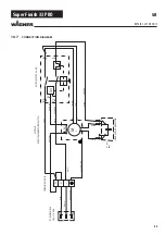
Page 19: ...yellow light blue MOTOR WITH TEMPERATURE SWITCH M 1 Z2 U2 OPERATION CAPACITOR C 35μF 400V black black 155 C N L Z1 U1 red green yellow blue black N MOTOR SWITCH 16A b U P1 P2 6 3 light blue blue black yellow 340380 2388609 2388608 b GB REPAIRS AT THE UNIT 10 7 CONNECTION DIAGRAM ...

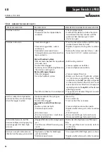
Page 20: ...ressure regulating valve three revolutions to the left possibly pull gently on the rotary knob Allow the unit to run one or two minutes After that turn pressure regulatingvalvetotherighttosetthedesired operating pressure Top up the oil and contactWagner Service to search for the leak Unit has sucked in and generates pressure but the pressure collapses when the trigger is pulled No tip mounted in t...

Page 21: ...57 Super Finish 33 PRO GB ...

Page 22: ...60 cm 0556 074 0556 075 0556 076 0556 077 10 Tip extension with slewable knee joint F thread 11 16 Length 100 cm Length 200 cm Length 300 cm 0096 015 0096 016 0096 017 Adapter 11 16 7 8 0555 300 11 Inline Roller 0345 010 12 Hopper 5l 0341 265 13 Hopper 20l 0341 266 14 Suction system flexible for dispersions 0034 630 15 Cleaning container for suction system with holder only for flexible suction sys...

Page 23: ...59 Super Finish 33 PRO SPARE PARTS AND ACCESSORIES GB 1 2 3 4 5 6 7 8 9 10 11 12 13 14 15 16 17 18 ...

Page 24: ... incl stainless steel hose DN6 1 4 10m Spraypack consisting of basic unit 2311659 Airless gun Vector Grip G thread incl Trade Tip 3 nozzle holder and 2SpeedTip L10 208 510 2311660 2311853 TempSpray H 226 ideal for dispersions materials with high viscosity Basic unit 1 4 incl Hose reel heated hose DN10 15m hose 1 4 DN4 1m Spraypack consisting of Basic unit 2311660 Airless un AG 14 G thread incl Tra...

Page 25: ...019 0 48 0 019 0 48 225 270 white white 0554519 0554619 Flame retardant 421 521 621 40 50 60 0 021 0 53 0 021 0 53 0 021 0 53 190 225 270 white white white 0554421 0554521 0554621 1 Spray width at about 30 cm to the object and 100 bar 10 MPa pressure with synthetic resin paint 20 DIN seconds HEA NOZZLES FOR LOW MIST SPRAYING AT LOW PRESSURE HEA stands for High Efficiency Airless an innovative nozz...

Page 26: ...13 0553413 0553513 0553613 0553813 Fillers Rust protection paints 115 215 315 415 515 615 715 815 10 20 30 40 50 60 70 80 0 015 0 38 0 015 0 38 0 015 0 38 0 015 0 38 0 015 0 38 0 015 0 38 0 015 0 38 0 015 0 38 100 120 150 190 225 270 300 330 yellow yellow yellow yellow yellow yellow yellow yellow 0553115 0553215 0553315 0553415 0553515 0553615 0553715 0553815 Rust protection paints Latex paints Di...

Page 27: ...e white white white white white white white white white white white white white white white white white white white white white white white white 0553225 0553325 0553425 0553525 0553625 0553725 0553825 0553227 0553327 0553427 0553527 0553627 0553827 0553229 0553329 0553429 0553529 0553629 0553231 0553331 0553431 0553531 0553631 0553731 0553831 0553233 0553333 0553433 0553533 0553633 0553235 055333...

Page 28: ...64 D7 Nozzles 113 417 Order no 0271 063 L10 Nozzles 208 510 Order no 0271 042 D10 Nozzles 111 419 Order no 0271 045 S10 Nozzles 527 235 Order no 0271 049 Medium L20 Nozzles 210 512 Order no 0271 043 D20 Nozzles 115 421 Order no 0271 046 S20 Nozzles 539 243 Order no 0271 050 Large L30 Nozzles 212 514 Order no 0271 044 D30 Nozzles 115 423 Order no 0271 047 S30 Nozzles 543 252 Order no 0271 051 X Lar...

Page 29: ...65 Super Finish 33 PRO GB ...

Page 30: ...ing 12 0341 702 Outlet valve service set 13 2342 946 Outlet valve complete 14 2383 994 Pressure gauge 15 0261 352 Mains cable H07 RNF 3x 1 5mm 6m long 16 2402 675 Cable threaded joint 17 2386 850 Label SF 33 Pro 18 0169 248 Relief valve compl 19 2344 692 Motor gasket 20 2386 858 Label right 21 9902 225 Oval head screw 3 5x9 5 22 2392 781 Fan cover 23 9930 114 Cylindrical pin 24 9901 105 Threaded p...

Page 31: ...67 Super Finish 33 PRO GB SPARE PARTS AND ACCESSORIES 1 2 3 4 6 7 8 9 10 12 5 11 13 15 16 17 14 18 19 20 21 22 23 24 25 26 27 28 30 29 Spare parts diagram SF 33 Pro ...

Page 32: ...ILTER Spare parts diagram high pressure filter 11 4 SPARE PARTS LIST TROLLEY Spare parts diagram trolley ITEM ORDER NO DESIGNATION 1 2399 672 High pressure filter HF 01 compl 2 0097 301 Filter block 3 0097 302 Filter housing 4 0097 306 Hollow screw 5 0097 304 Seal ring 6 9970 110 Seal ring 7 9974 027 O ring 30x2 PTFE 8 9971 401 O ring 16x2 PTFE 9 0508 749 Bearing spring 10 0508 603 Bearing ring 11...

Page 33: ... ACCESSORIES Spare parts diagram suction system ITEM ORDER NO DESIGNATION 0034 630 Suction system assy 1 0034 607 Suction hose compl 2 0034 633 Return tube compl 3 0036 580 Filter basket compl 4 0036 586 Filtersieb 5 0036 581 Filter sieve 6 0036 582 Filter basket base 2 3 1 4 5 6 ...

Page 34: ...PARTS LIST HOPPER 5 LITRES Spare parts diagram hopper 5 L 3 2 1 4 5 11 7 SPARE PARTS LIST HOPPER 20 LITRES 2 3 4 5 6 7 1 8 10 9 ITEM ORDER NO DESIGNATION 0341 266 Hopper 20 litres assy 1 0097 269 Hopper without cover 2 0097 270 Cover 3 9902 306 Sheet metal screw 3 9x13 2 4 0097 521 Filter disk mesh width 0 8 mm 5 9922 609 Securing ring 37 x 1 5 6 0037 776 Pressure spring 7 9941 509 Ball 30 8 0097 ...

Page 35: ...subject to strict checks under Wagner quality assurance Wagner exclusively issues extended guarantees to commercial or professional users hereafter referred to as customer who have purchased the prod uct in an authorised specialist shop and which relate to the products listed for that customer on the Internet under www wagner group com profi guarantee The buyer s claim for liability for defects fr...

Page 36: ...d by using accessory parts additional components or spare parts that are not original Wagner parts for products to which modifications or additions have been carried out for products where the serial number has been removed or is illegible for products to which attempts at repairs have been carried out by unauthorised persons for products with slight deviations from the target properties which are...

Page 37: ...1 Telefax 41 71 7 57 22 22 wagner wagner group ch F Euromair Antony S A V Ile de France 12 14 av F Sommer 92160 Antony Tel 01 55 59 92 42 Telefax 33 0 1 69 81 72 57 conseil paris euromair com NL WSB Finishing Equipment BV De Heldinnenlaan 200 3543 MB Utrecht Netherlands Tel 31 30 241 41 55 Telefax 31 30 241 17 87 info wagner wsb nl D J Wagner GmbH Otto Lilienthal Straße 18 D 88677 Markdorf Postfac...

Reviews: