background image

2.

General view of application

2.1

Application

All painting jobs in the workshop and on the building 
site, small dispersion work with the spray gun or inter-
nally fed Airless roller.  

Examples of objects of spraying

Doors, door frames, balustrades, furniture, wooden
cladding, fences radiators (heating) and steel parts, inter-
nal ceilings and walls.

2.2

Coating materials

Processible coating materials

Dilutable lacquers and paints or those containing sol-
vents, two-component coating materials, dispersions, la-
tex paints.

No other materials should be used for spraying without
WAGNER’s approval.

Filtering

Despite suction filter and insertion filter in the spray gun,
filtering of the coating material is generally advisable.

Stir coating material before commencement of work.

Viscosity

With this unit it is possible to process highly viscous
coating materials of up to around 20.000 MPa·s.

If highly viscous coating materials cannot be taken in by
suction, they must be diluted in accordance with the 
manufacturer’s instructions.

Two-component coating material

The appropriate processing time must be adhered to ex-
actly. Within this time rinse through and clean the unit
meticulously with the appropriate cleaning materials.

Coating materials with sharp-edged additional 
materials

These have a strong wear and tear effect on valves,
high-pressure hose, spray gun and tip. The durability of
these parts cane be reduced appreciably through this.

Attention: 

Make sure, when stirring up with

motor-driven agitators that no air bubbles
are stirred in. Air bubbles disturb when
spraying and can, in fact, lead to interruption
of operation.

i

Pay attention to the  Airless quality of the
coating materials to be processed.

i

3. Description of unit

3.1

Airless process

The main areas of application are thick layers of highly
viscous coating material for large areas and a high con-
sumption of material.

A piston pump takes in the coating material by suction
and conveys it to the tip. Pressed through the tip at a
pressure of up to a maximum of 230 bar (23 MPa), the
coating material is atomised. This high pressure has the
effect of micro fine atomisation of the coating material.

As no air is used in this process, it is described as an
AIRLESS process.

This method of spraying has the advantages of finest
atomisation, cloudless operation and a smooth, bubble-
free surface. As well as these, the advantages of the
speed of  work and convenience must be mentioned.

3.2

Functioning of the unit

In the following there is a short description of the techni-
cal construction for better understanding of the function.

WAGNER ProSpray units are electrically driven high-
pressure spraying units.

A gear unit transfers the driving force to a crankshaft.
The crankshaft moves the pistons of the material feed
pump up and down. 

The inlet valve is opened automatically by the upwards
movement of the piston. The outlet valve is opened
when the piston moves downward.

The coating material flows under high pressure through
the high-pressure hose to the spray gun. When the coat-
ing material exits from the tip it atomizes.

The pressure regulator controls the volume and the oper-
ating pressure of the coating material.

ProSpray 22

g

General view of application

Description of unit

Summary of Contents for ProSpray 22

Page 1: ...Operating manual Airless high pressure spraying unit ProSpray 22...

Page 2: ...be used 2 Secure WAGNER spray gun using the safety catch on the trigger 3 Ensure that the unit is properly earthed The connection must take place through a correctly earthed two pole and earth socket...

Page 3: ...ion filter 35 8 3 Cleaning Airless spray gun 35 Page 9 Remedy in case of faults 36 10 Servicing 38 10 1 General servicing 38 10 2 High pressure hose 38 11 Repairs at the unit 38 11 1 Relief valve 38 1...

Page 4: ...ting material or solvents consult a doctor for quick and correct treatment Inform the doctor about the coating material or solvent used Danger Danger Danger Danger P Secure spray gun against unintende...

Page 5: ...wind Set the unit up in such a way that vapors containing solvents do not reach the unit and build up there A minimum distance of 5 m between the unit and spray gun is to be maintained P Ventilation...

Page 6: ...are stirred in Air bubbles disturb when spraying and can in fact lead to interruption of operation i Pay attention to the Airless quality of the coating materials to be processed i 3 Description of un...

Page 7: ...f valve Lever position vertical PRIME k circulation Lever position horizontal SPRAY p 9 ON OFF switch 10 Control system cover 11 Digital Electronic Spray Control ESC system 12 Control panel indicators...

Page 8: ...necting thread M 16 x 1 5 Dimensions L x W x H 480 x 345 x 405 mm Max sound pressure level 80 dB A Place of measuring 1 m in distance from the unit and 1 6 m above the floor 12 MPa 120 bar operating p...

Page 9: ...e proper pressure setting for spraying stain lacquer varnish and multi colors If the pressure indicator goes to solid yellow when the pressure is set so that it starts at solid green it indicates one...

Page 10: ...ting container 5 3 1 2 4 The unit must be connected to an appropriately grounded safety outlet Attention 4 6 Taking the unit into operation with coating material 1 Immerse suction hose Fig 6 Pos 1 and...

Page 11: ...s the functionality of the sprayer It is installed directly below the pressure control knob on the control panel It consists of a display and four function keys The display shows various menu screens...

Page 12: ...prayer will operate If the wrong code is entered the display will continue to ask for the correct code and the sprayer will be disabled To set or change the security code press the 2 key Enter the old...

Page 13: ...circult through pane trating water Never spray down the unit with high pressure or high pressure steam cleaners Danger First of all pull out mains plug from socket Danger Caution Do not pump or spray...

Page 14: ...is in the SPRAY p spray position Packings sticky or worn Valve balls worn Valve seats worn Upper packing is worn Piston is worn Check voltage supply Turn up pressure control knob Replace Set relief v...

Page 15: ...ective Take the sprayer to a Wagner authorized service center for repair Low Voltage Screen E4 The Low Voltage screen appears when the sprayer shuts down because of low input voltage Check the power s...

Page 16: ...shaft 7 and in the relief valve handle 2 into alignment 7 Insert the grooved pin 1 to secure the relief valve handle in position 1 7 5 6 4 2 3 Switch the unit OFF Before all repair work Unplug the pow...

Page 17: ...ig 10 Item 1 10 11 12 8 7 11 3 Packings 1 Remove inlet valve housing in accordance with the steps in Chapter 11 2 Page 38 2 It is not necessary to remove the outlet valve 3 Slide the retaining ring 10...

Page 18: ...pump manifold 18 Remove installation tool from piston 3 19 Carefully tighten retainer nut 6 with adjusting wrench 20 Position the pump manifold 2 underneath the gear unit housing and push up until it...

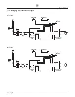
Page 19: ...anel Board Surge Suppressor Electronic Pressure Control EPC J16 AC Motor AC Neut AC Line AC Motor J9 J2 J1 J12 J7 Switch Ground 120 V AC Potentiometer Motor Pressure Sensor Pressure Sensor Jumper Plug...

Page 20: ...nium model 0335 002 Spray gun G 12 aluminium model 0257 001 Spray gun AG 09 S stainless steel model 2 0096 004 Pole gun 30 cm 0096 019 Pole gun 100 cm 0096 005 Pole gun 150 cm 0096 006 Pole gun 270 cm...

Page 21: ...ushing 14 0508 739 Lower seal 15 0508 677 Lower ball guide 16 0508 678 Inlet valve ball 17 0508 679 Inlet valve seat 18 3500 203 O ring 19 0508 680 Inlet valve housing 20 0508 615 Plug 21 0508 740 Sea...

Page 22: ...Page 100 12 4 Spare parts list for drive assembly spare parts diagram see Page 99 Item Order No Description 1 0551 616 Ventilator 2 9850 936 ON OFF switch 3 0508 571 Screw 4 4 0551 518 Front cover 5...

Page 23: ...rget the fact that the hard metal insert is brittle Never throw the tip or handle with sharp metal objects The following points must be observed to keep the tip clean and ready for use 1 Open the reli...

Page 24: ...48 320 0090 719 1088 719 0552 719 819 80 0 019 0 48 400 0090 819 1088 819 0552 819 Mica paints 221 20 0 021 0 53 145 0090 221 1088 221 0552 221 Zinc dust paints 421 40 0 021 0 53 190 0090 421 1088 42...

Page 25: ...Fax 43430528 A B Wagner Spraytech Iberica S A Apartado 132 08750 Molins de Rey Barcelona Spain Phone 93 6800028 Fax 93 6800555 J Wagner France S A R L B P 75 91122 Palaiseau Cedex France Phone 01 601...

Page 26: ...96 ProSpray 22 d Zubeh rbild g Accessories illustration f Illustration des accessoires i Figura degli accessori 3 1 5 2 4 6 ProSpray 22...

Page 27: ...9 10 8 2 14 13 12 11 ProSpray 22 d Hauptbaugruppe g Main Assembly f Ensemble principal i Gruppo principale Ersatzteilbild Spare parts diagram Illustration des pi ces de rechange Figura dei ricambi Pro...

Page 28: ...8 9 10 11 12 13 14 15 16 17 18 19 2 3 4 5 20 21 22 ProSpray 22 d Farbstufe g Fluid section f Pompe peinture i Stadio della vernice Ersatzteilbild Spare parts diagram Illustration des pi ces de rechang...

Page 29: ...8 10 11 12 13 14 15 16 ProSpray 22 d Baugruppe Antrieb g Drive Assembly f Ensemble moteur i Gruppo azionamento Ersatzteilbild Spare parts diagram Illustration des pi ces de rechange Figura dei ricambi...

Page 30: ...3 4 6 5 ProSpray 22 d Gestell g Frame f Support i Telaio ProSpray 22 d Ansaugsystem g Suction system f Syst me d aspiration i Sistema di aspirazione Ersatzteilbild Spare parts diagram Illustration de...

Page 31: ...uns schriftlich mitzuteilen Wir behalten uns vor die Garantie durch ein Vertragsunternehmen erf llen zu lassen Die Leistung dieser Garantie ist abh ngig vom Nachweis durch Rechnung oder Lieferschein...

Page 32: ...eclare that the supplied version of WAGNER ProSpray 22 Complies with the following provisons applying to it 73 23 EEC 89 336 EEC 92 31 EEC 93 68 EEC 98 37 EEC Applied harmonized standards in particula...

Reviews: