34
Plast Coat HP 30
EN
COMMISSIONING
6.4
BEGINNING OF THE SPRAYING PROCESS
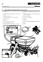
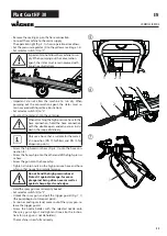
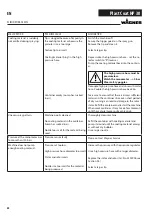
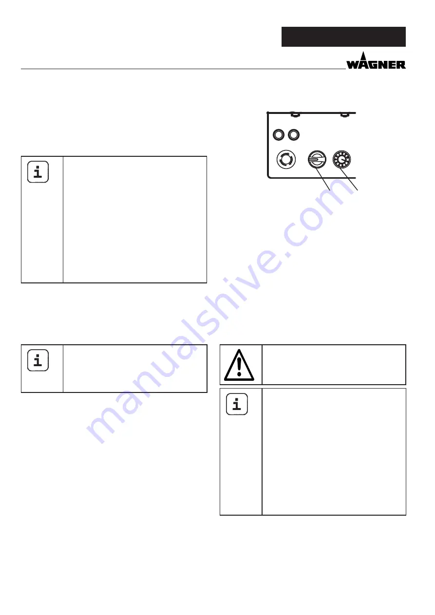
• Use the pressure regulator (Fig. 8, 3) on the control unit to
set the required working pressure to level 10.
• Pull the trigger guard on the spray gun to start the pump.
• Reduce the operating pressure so that the spray pattern is
still satisfactory.
If there is too little material / liquid in the
container, the pump speed will be reduced
in order to minimise damage to the PC HP
30. Refill the container immediately since
even short periods of dry running can lead
to damage to the rotor / stator.
If the container is not refilled within ap-
prox. 20 seconds, the pump switches itself
off automatically in order to prevent more
serious damage. After refilling, the pump
must be restarted again.
After an interruption, it may take a few mo-
ments until the material starts to come out
evenly again (spray test recommended).
6.5
INTERRUPTIONS OF WORK / BREAKS
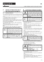
• Release the trigger guard.
• Move the selector switch (Fig. 8, 2) to „R“ to release the pres-
sure (pressure gauge shows 0 bar).
• Set selector switch (fig. 8, 2) to “0”.
Ensure that the pump area is filled with
material or conservation agent so that the
stator does not jam on the rotor. Always also
observe the pot time / curing time of the
material.
3
POWER
ERROR
PRESSURE
R
0
F
2
6.6
END OF THE SPRAYING PROCESS / END OF WORK
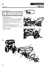
• Release the trigger guard.
• Move the selector switch (Fig. 8, 2) to „R“ to release the pres-
sure (pressure gauge shows 0 bar).
• Set selector switch (fig. 8, 2) to “0”.
Always lock the trigger guard at the end of
the spraying process.
In the event of interruptions of work up to a
maximum of 14 days and if the same material
is being reused (always note the material‘s pot
life / curing time), complete cleaning of the PC
HP 30 is not required.
Ensure that the rotor and stator are fully cove-
red with material and close the container with
film and the cover (Art. No. 2400030) so it is as
air-tight as possible.
In the event of a material change or if the PC
HP 30 is to be out of service for a prolonged
period, clean it in accordance with the instruc-
tions in Section 8 in order to prevent the rotor
from getting stuck in the stator.
Summary of Contents for PLAST COAT HP 30
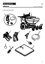
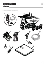
Page 45: ...45 Plast Coat HP 30 EN PlastCoat HP 30 Accessories illustration 1 9 11 10 5 6 8 2 3 4 7 8 13...
Page 67: ...67 Plast Coat HP 30 DA PlastCoat HP 30 Tilbeh rsbillede 1 9 11 10 5 6 8 2 3 4 7 8 13...
Page 89: ...89 Plast Coat HP 30 SV 1 9 11 10 5 6 8 2 3 4 7 8 13 PlastCoat HP 30 Tillbeh rsbild...

